Intelligent Motion Systems MForce PowerDrive Plus MForce Series Microstepping PowerDrive User Manual
Page 39
21
Part 2: Interfacing and Configuring
T
DSU
T
DH
T
SH
T
SL
Direction
Step
T
DC
T
CHL
T
CHL
Channel A
Channel B
Direction Change
T
SH
T
SL
T
DC
T
SH
T
SL
T
DC
Step Up
Step Down
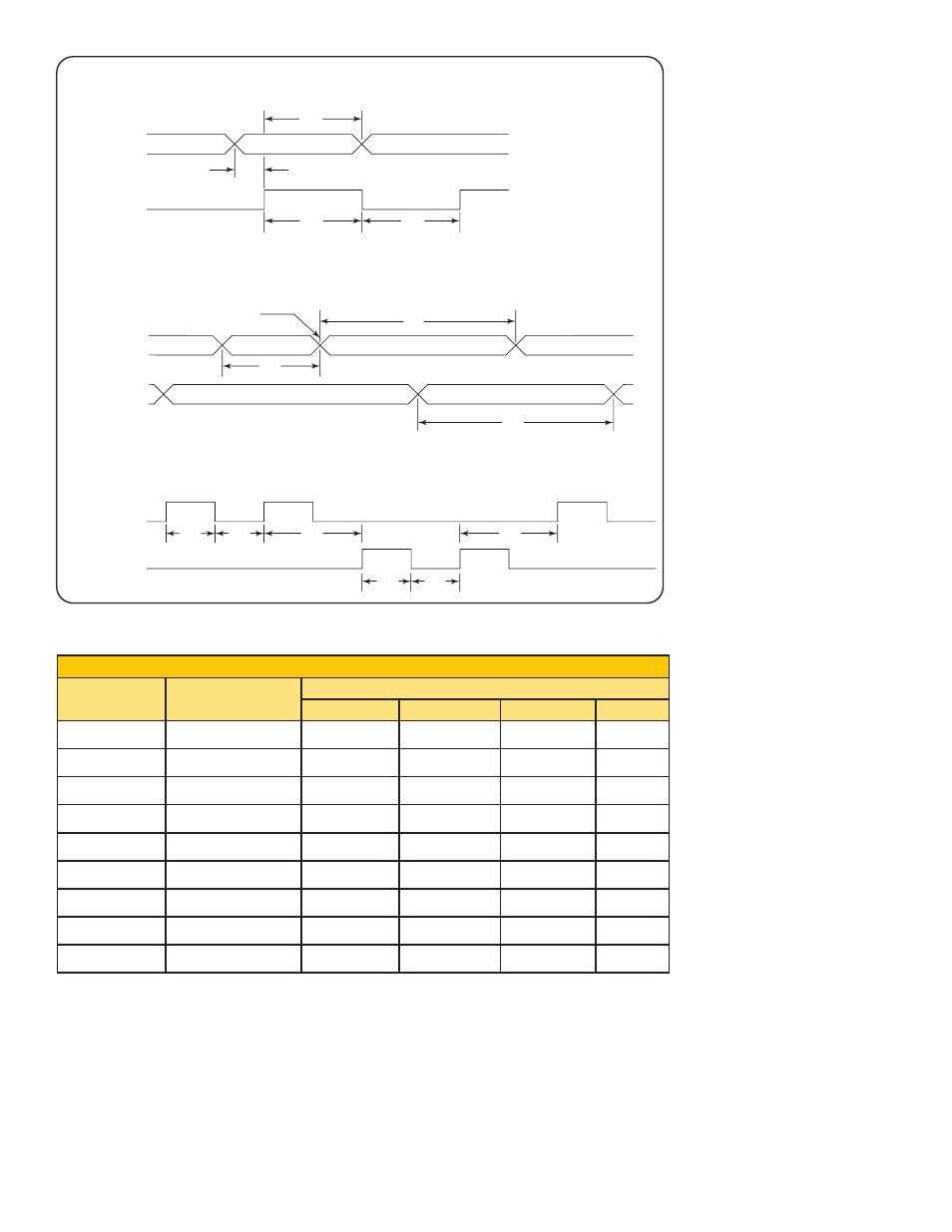
STEP/DIRECTION TIMING
QUADRATURE TIMING
UP/DOWN TIMING
Figure 2.4.3: Clock Input Timing Characteristics
Clock Input Timing
Symbol
Parameter
Type and Value
Step/Direction Step Up/Down
Quadrature
Units
T
DSU
T Direction Set Up
50
—
—
nS min
T
DH
T Direction Hold
100
—
—
nS min
T
SH
T Step High
100
100
—
nS min
T
SL
T Step Low
100
100
—
nS min
T
DL
T Direction Change
—
200
200
nS min
T
CHL
T Channel High/Low
—
—
400
nS min
F
SMAX
F Step Maximum
5
5
—
MHz Max
F
CHMAX
F Channel Maximum
—
—
1.25
MHz Max
F
ER
F Edge Rate
—
—
5
MHz Max
Table 2.4.1: Input Clocks Timing Table