Making connections, Optional audio connections, Making stereo audio connections – Integra DPC-5.2 User Manual
Page 16: Digital connections
16
SN 29343266 DPC-5.2
AC INLET
COMPONENT
VIDEO OUTPUT
AUDIO
OUTPUT
DIGITAL OUTPUT
VIDEO
S VIDEO
P
B
P
R
Y
L
R
RS 232
DVD CHANGER
MODEL NO.
DPC-5.2
OPTICAL
COAXIAL
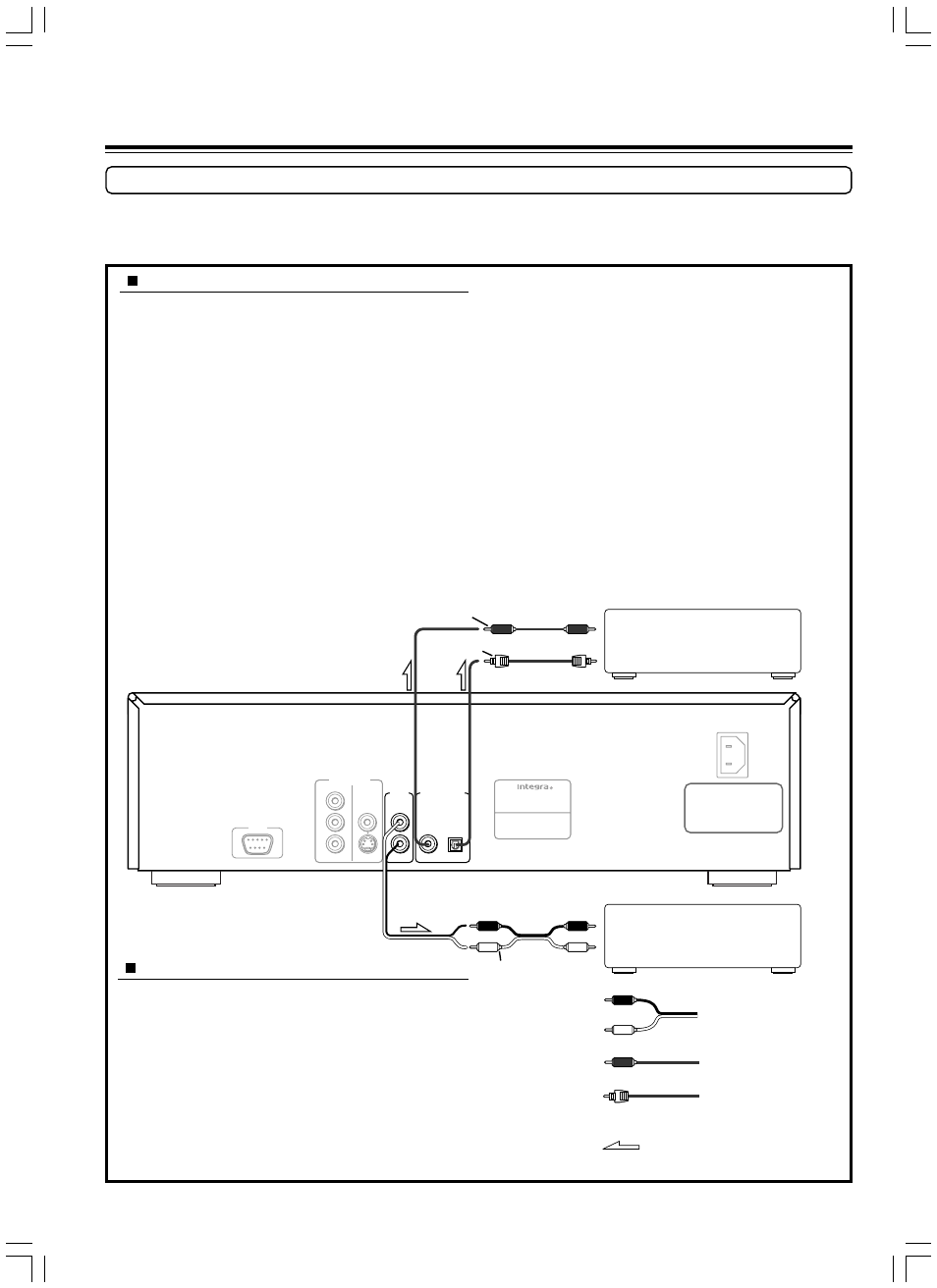
Optional Audio Connections
This DVD Changer provides numerous ways to take full advantage of the digital multi-channel sound recorded on DVD and some CD media.
Be sure to set Digital Audio Out after connection using the setup menu explained in “Customizing the Settings” starting
on page 30.
Signal flow
Making stereo audio connections
Using an audio cable (sold separately), make audio connections
from the AUDIO OUTPUT L and R jacks to the corresponding
jacks on the stereo component.
Be sure to set Digital Audio Out setting to “PCM” using the setup
menu explained in “Customizing the Settings” starting on page 30.
See page 35 for direct information.
Notes
• Be sure to match the colors of the plugs on the cable with the
corresponding jacks on the DVD Changer and the stereo component: red
for R (right) audio and white for L (left) audio.
• Do not make connections to the PHONO or TUNER jacks on the stereo
component.
DO NOT connect the
power cord until all
connections are
complete.
Making Connections
Digital connections
Make digital connections from the DVD Changer to an AV
component that features digital input capability or one or more
multi-channel audio decoders to realize the full cinematic
experience made possible by the DVD format. This DVD Changer
features optical and coaxial digital audio output jacks and can
output Dolby Digital and DTS bitstreams as well as outputting
standard PCM.
Make connections from the DIGITAL OUTPUT OPTICAL jack to
the digital optical input jack on the AV component using an optical
fiber cable (sold separately). Make connections from the DIGITAL
OUTPUT COAXIAL jack to the digital coaxial input jack on the
AV component using a coaxial cable (sold separately). It is not
necessary to make more than one type of digital connection to a
single component.
When you are making connections to an amplifier or receiver that
has internal Dolby Digital or DTS decoding capabilities, set Digital
Audio Out to “Dolby Digital” or “DTS” using the setup menu
explained in “Customizing the Settings” starting on page 30. See
page 35 for direct information.
When you are making connections to an amprifer or receiver that
has digital input capabilities, but no internal decoder, set Digital
Audio Out to “PCM” using the on-screen menu explained in
“Customizing the Settings” starting on page 30. See page 35 for
direct information. Setting Digital Audio Out to any other setting
could result in digital noise being output that could cause harm your
hearing and may also damage your speakers.
Notes
• Refer to the instructions supplied with the AV component for details on
what digital audio formats it is compatible with.
• Even if digital audio connections are made, it is also recommended to
make analog connections, because some conditions or media may prohibit
digital audio output.
Analog signal
Audio (R)
Audio (L)
Digital signal
Digital signal
Coaxial plug
Optical plug
An amplifier or receiver with a
Dolby Digital or DTS decorder or
digital inputs
An amplifier or receiver
with stereo inputs
Audio cable (not supplied)
To digital
input (optical)
Coaxial cable (not supplied)
To audio input
Optical cable (not supplied)
To digital
input (coaxial)