Setting up your snow thrower, Warning – MTD 769-04101 User Manual
Page 8
8
3
Setting Up
Your Snow
Thrower
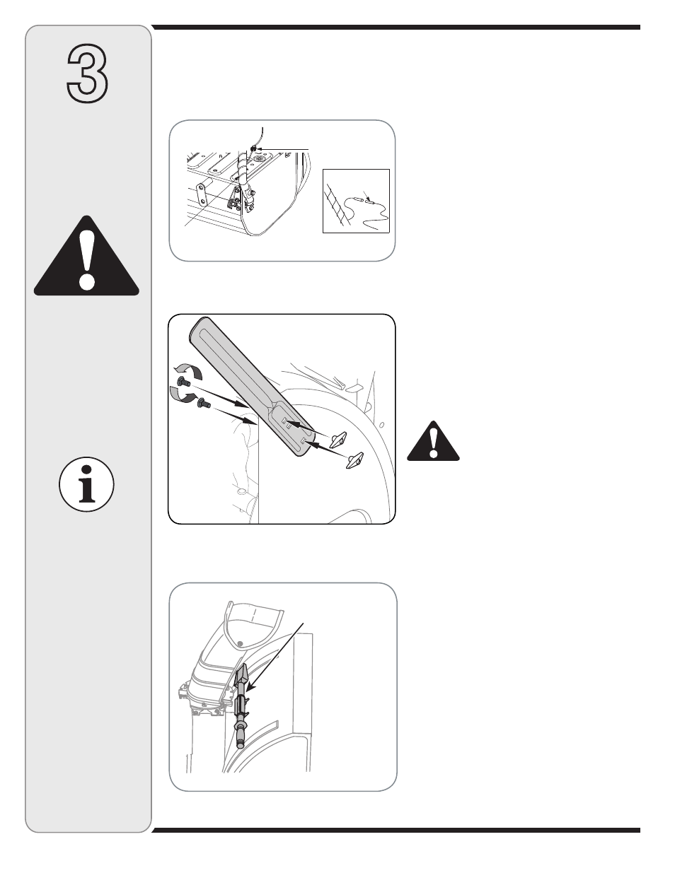
Drift Cutters
(If Equipped)
Drift cutters should be used when operating the snow
thrower in heavy drift conditions.
• On models so equipped, drift cutters and hardware
are assembled to the auger housing inverted.
• Remove the carriage bolts and wingnuts securing the
drift cutters to the housing.
• Reposition drift cutters so they face forward as
shown in Figure 3-9. Secure with hardware previously
removed, wingnuts should be fastened on the
outside
of the housing as shown.
If your unit is
not equipped with drift cutters, you may
contact Customer Support as instructed on page 2 for
information regarding price and availability.
Snowthrower Model Drift Cutter Kit:
All models
OEM-390-679
Clean-Out Tool
The clean-out tool is mounted to the rear of the auger
housing and is designed to clear a clogged chute. See
Figure 3-10. Refer to the Operation section for more
detailed information regarding the chute clean-out tool.
NOTE: This item is fastened with a cable tie to the rear of
the auger housing at the factory. Cut the cable tie before
operating the snow thrower.
WARNING: Never use your hands to
clean snow and ice from the chute
assembly or auger housing.
Final Adjustments
Make these final adjustments before operating your snow
thrower for the first time. Failure to follow these instruc-
tions may cause damage to the snow thrower.
Wheel Drive Control & Shift Lever
Perform the following test to determine need for adjust-
ment:
• Move the shift lever into sixth (6) position. See Figure
3-14.
• With the drive control released (see Figure 3-11A),
push the snow thrower forward, then pull it back. The
machine should move freely.
• Engage the drive control and attempt to move the
machine both forward and back, resistance should be
felt.
• Move the shift lever into the fast reverse (R2) position
and repeat the previous two steps.
If you experienced resistance rolling the unit, either
when repositioning the shift lever from 6 to R2 or when
attempting to move the machine with the drive control
released, adjust the drive control immediately. To adjust,
proceed as follows:
WARNING
Never use your hands
to clean snow and
ice from the chute
assembly or auger
housing.
IMPORTANT
Under any circum-
stance do not exceed
manufacturer’s recom-
mended psi. Equal tire
pressure should be
maintained at all times.
Excessive pressure
when seating beads
may cause tire/rim
assembly to burst
with force sufficient to
cause serious injury.
Refer to sidewall of
tire for recommended
pressure.
Figure 3-10
Clean-Out
Tool
Figure 3-9
Alternator Lead
Lamp Wire
Alternator
Lead
NOTE:
Wheels are omitted from illustration for clarity.
Figure 3-8
Lamp Wiring
• Wrap the wire from the head lamp down the right
handle until the wire can be plugged into the alterna-
tor lead wire under the fuel tank. See Figure 3-8.