Meade Instruments 4504 User Manual
Page 12
page 12
1
2
6
5
4
7
8
3
10
11
12
9
13
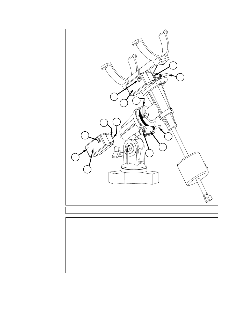
Fig. 11: Motor drive system assembly.
1. R.A. Worm Shaft
2. (R.A. Axis) Plastic Adapter
3. Aluminum Shaft
4. Set Screw
5. Circular Housing containing
notched plastic shaft
6. Battery Pack Connector
7. LED
8. R.A. Motor Drive
9. Handbox (HBX) Port
10. Dec Motor Drive
11. R.A. Lock
12. Dec Worm Shaft
13. Set Screws
Key to Figure 11
See also other documents in the category Meade Instruments Optical devices:
- DS-2090AT-TC (20 pages)
- CV-5 (32 pages)
- RB-70 (20 pages)
- 70AZ-TR (7 pages)
- 60EQ-D (11 pages)
- 114EQ-AR (28 pages)
- Astro-Tech AT66ED (2 pages)
- Astro-Tech AT80ED (2 pages)
- TMB Optical TMB-130 (2 pages)
- 114 EQ-ASB (16 pages)
- 60AZ-A2 (20 pages)
- Astro-Tech AT 127EDT (2 pages)
- ETX-80AT-TC (44 pages)
- 70AZ-T (7 pages)
- ETX-90PE (60 pages)
- RB-60 (24 pages)
- LT ACF Series (52 pages)
- 50 AZ-T (16 pages)
- 114 EQ-DS (16 pages)
- RCX400TM (74 pages)
- 8" LS-8 SC (47 pages)
- 6" LS-6 ACF (45 pages)
- 60AZ-A (8 pages)
- 114ST EQ-D (16 pages)
- 626-3233 (16 pages)
- LX200GPS-SMT (73 pages)
- 4500 (16 pages)
- 60AZ-AR (20 pages)
- 60 (8 pages)
- LXD 75 (68 pages)
- 80EQ-AR (22 pages)
- Astro-Tech AT102EDF (2 pages)
- LX200GPS (72 pages)
- 70AZ-AR (20 pages)
- CV-4 8 x 30 (34 pages)
- Binocular and Digital Camera (10 pages)
- Starfinder 12.5 (12 pages)
- Astro-Tech AT90EDT (2 pages)
- CV-6 (36 pages)
- Astro-Tech AT80EDT (2 pages)
- Starfinder 16 (16 pages)
- RCX400 (76 pages)
- RCX400 (1 page)
- 60AZ-D (8 pages)
- Telestar 40AZ-T (8 pages)