Onyx 800r features, Front panel, Gain control – MACKIE 800R User Manual
Page 10: Mic/line switch, Mic impedance switch (channels 1 and 2), Phase switch, Low-cut switch, Onyx 800r
10
ONYX 800R
ONYX 800R
Onyx 800R Features
Front Panel
There are eight channels in the Onyx 800R. They
all share the same features with the exceptions that
channels 1 and 2 have an impedance select switch and
a mid/side decode switch, and channels 7 and 8 have a
high-impedance 1/4" input jack for connecting electric
instruments directly to the preamp without a direct box.
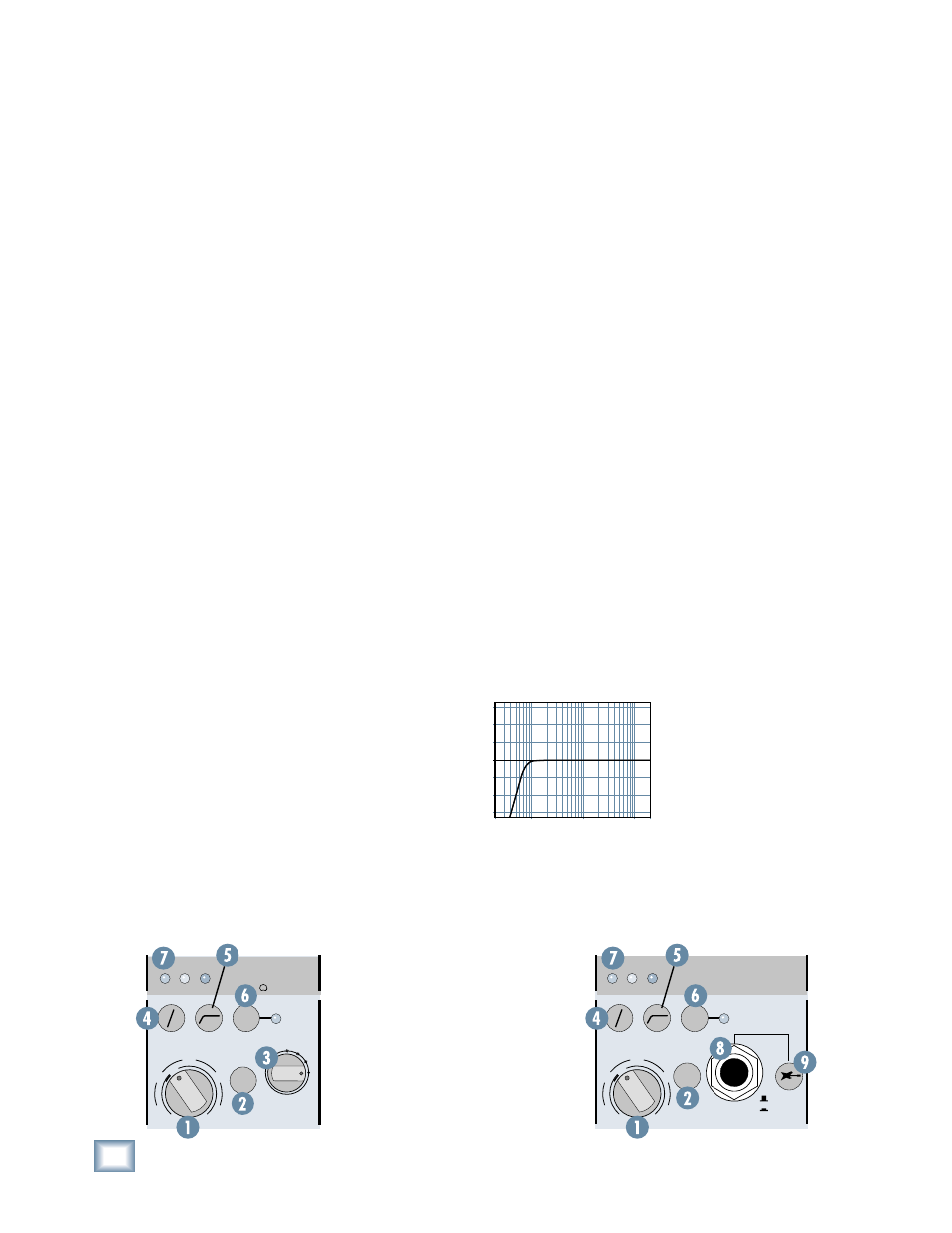
1. GAIN Control
The GAIN control adjusts the input sensitivity of the mic
and line inputs. This allows the signal from the outside
world to be adjusted to optimal internal operating levels.
If the signal is plugged into the XLR jack, there is 0 dB
of gain (unity gain) with the knob turned all the way
down, ramping up to 60 dB of gain fully up.
When connected to the balanced line input (DB25
connector), there is 20 dB of attenuation all the way
down, and 40 dB of gain fully up, with a “U” (unity gain)
mark at about 10:00.
2. MIC/LINE Switch
This button selects the input source from either the
XLR MIC inputs or the DB25 LINE inputs. When the but-
ton is out, the XLR MIC input is used and the line input
is disconnected. When the button is pushed in, the DB25
LINE input is used and the XLR MIC input is disconnect-
ed. This way, you can leave signals connected to both
inputs without having to disconnect one or the other,
and the 800R acts as a patchbay for your input sources.
3. MIC IMPEDANCE Switch
(Channels 1 and 2)
Many classic, vintage, and ribbon microphones are very
sensitive to the input impedance of the mic preamp, and
operate best at specifi c impedances. The MIC IMPED-
ANCE switch allows you to change the input impedance
of the microphone inputs on channels 1 and 2. This
allows you to change the characteristics of the sound of
the microphone.
There are four selections to choose from: A: 300 ohms,
B: 500 ohms, C: 1300 ohms, and D: 2400 ohms. Select the
impedance that is closest to the recommended imped-
ance for your microphone. Or you can experiment with
different settings and decide which one sounds best for
your particular application.
Note: The 2400 ohm position (D) matches the nomi-
nal input impedances of channels 3-8.
4. Phase Switch
Pushing in this switch simply reverses the polarity of the
signal. This provides an easy way to correct a microphone
whose polarity is opposite from the other microphones,
either from a miswired cable or from not following the AES
standard for Pin 2/Pin 3.
5. Low-Cut Switch
The Low-Cut switch, often referred to as a high-pass
fi lter, cuts bass frequencies below 75 Hz at a rate of 18 dB
per octave.
In live situations, this is
useful for removing micro-
phone handling noise or
stage rumble. It can also be
used to reduce the “prox-
imity effect” with certain
microphones that accentu-
ates the bass frequencies
when a vocalist gets too
close to the microphone.
20
Hz
100
Hz
1k
Hz
10k
Hz
20k
Hz
–15
–10
–5
0
+5
+10
+15
Low Cut
Channel 1
MIC
IMPEDANCE
+
40dB
U
-
20dB
U
20
30
40
60
GAIN
A
B
C
D
1
1
MID
OL
0
-20
MID
OL
0
-20
300
Ω
500
Ω
1300
Ω
2400
Ω
A
B
C
D
48V
LINE
0
UNBAL
+
40dB
U
-
20dB
U
20
30
40
60
GAIN
HI-Z (INST)
MIC/LINE
HI-Z
8
8
OL
0
-20
OL
0
-20
48V
LINE
0
Channel 8