Typical installations fig. 6 – Marley Engineered Products 898L User Manual
Page 3
GROUND
SCREW
OUTLET BOX
EARTH
GROUND
120VAC
60Hz
SUPPLY
Fig. 5 - Wiring Diagram
CAUTION
BE SURE ALL WIRING COMPLIES WITH
LOCAL AND NATIONAL ELECTRICAL CODES AND
HOUSING IS PROPERLY GROUNDED.
TO INSTALL IN EXISTING HOMES
1. Determine location of ventilator. Check wall for studs
and obstructions.
2. Working inside wall first, draw a circle 9
1
⁄
8
” in diameter
at determined location. Be sure opening is at least one
inch from studs. (See Figure 2.)
3. Carefully saw opening in plaster. Remove just enough
insulation to allow sleeve to pass through, exposing
sheathing. Mark center of the hole on the sheathing. At
this point, drill small hole to outside.
4. Now work from the outside. Using hole as a center
point, draw a circle on outside wall 9
1
⁄
8
” in diameter.
Saw opening. In case of brick or stone, use hammer
and chisel to make opening. (See Figure 6.)
5. Install door and outside sleeve assembly from outside.
Caulk and level before nailing tight. Remove tape, per-
mitting damper door to open. (See Figure 3.)
6. Working from inside the house, slide inside sleeve into
place temporarily. Determine whether to remove one or
both knockouts from outside sleeve, permitting outlet box
to drop through. Remove knockouts from outside sleeve.
(See Figure 4.)
7. Slide inside sleeve into place again and pull power
cable through outlet box opening. This will determine
length of power cable to ventilator. Power line should be
run to switch box holding toggle switch. For more efficient
operation, an optional timer is available. Attach cable to
outlet box, using approved connector, and splice cable to
receptacle leads in outlet box cover. Ground wire may be
attached to grounding bolt in outlet box. (See Wiring
Diagram, Figure 5.)
8. Adjust inside sleeve so that flange is flush with finished
wall. Using metal screws, fasten inside housing to
outside housing. Screws are supplied with ventilator.
9. Perform Steps 6-8 as for new homes to finish
installation.
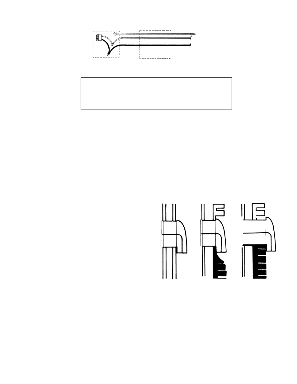
TYPICAL INSTALLATIONS
Fig. 6
STANDARD WALL SWITCH
- 3 -