Junction box mounting, Lamp mounting, Fan power cable connection – Multiquip Light Tower Mount Type Balloon Light GB2000 User Manual
Page 26: Balloon power cable, Figure 19. junction box mounting, Figure 20. fan/balloon power cable connections
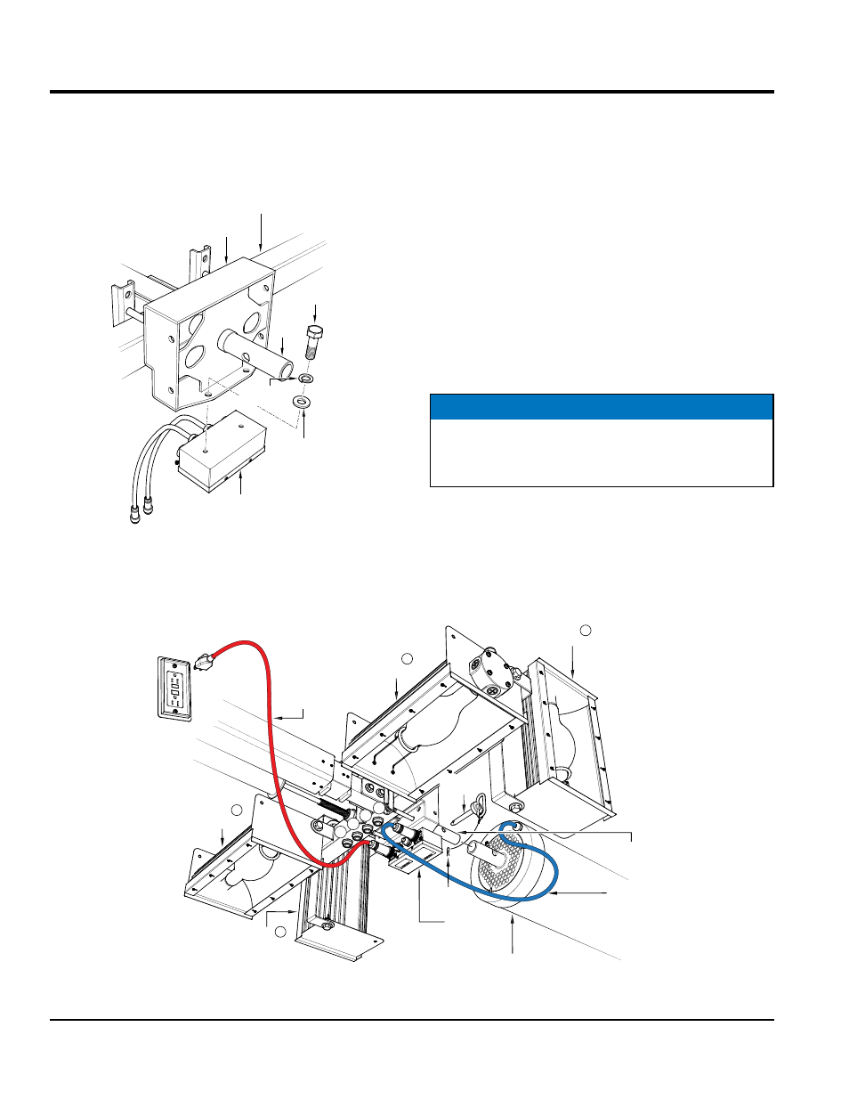
page 26 —gb2000 balloon lighT• operaTion and parTs manual — rev. #3 (08/30/12)
type 2 setup (s/n G1900119 and abOve)
JunCTion box mounTing
1. Secure the junction box (Figure 19) to the adapter plate
using the supplied bolts (2), lock washer (2), and flat
washer (2). Tighten mounting bolts securely.
Figure 19. Junction Box Mounting
BOLT
(2)
LOCK
WASHER (2)
FLAT
WASHER
(2)
JUNCTION BOX
LAMP
ADAPTER
PLATE
T-BAR
POLE
lamp mounTing
1. Place the GB2000 lamp fixture onto the lamp adapter
plate pole as shown in Figure 20.
2. Insert locking pin into hole opening on pole, then insert
cotter pin to lock pin in place.
Fan poWer Cable ConneCTion
1. Insert the 38 ft. (11.5 meters), 3-prong AC power plug
on the fan power cable as shown in Figure 20 into the
GFCI power receptacle on the generator.
2. Connect the other end of the fan power cable (quick
disconnect end) to the 3-pin AC power receptacle on
the junction box.
balloon poWer Cable
1. Connect the balloon power cable (Figure 20) to the
10-pin receptacle on the junction box.
NOTICE
Once the tower is raised and in position, the fan power
cable should be secured in such a way as to prevent
tripping and entanglement.
Figure 20. Fan/Balloon Power Cable Connections
LAMP
1
LAMP
3
LOCKING
PIN
BALLOON FIXTURE
FAN
POWER
CABLE
JUNCTION
BOX
J4
J3
J2
J1
COTTER
PIN
GFCI
LAMP
2
(TOP)
(BOTTOM)
(BOTTOM)
LAMP
4
(TOP)
2 FT. (10 PIN)
BALLOON
POWER CABLE
PLATE
ADAPTER
POLE