Meyer Sound MM-10 User Manual
Page 46
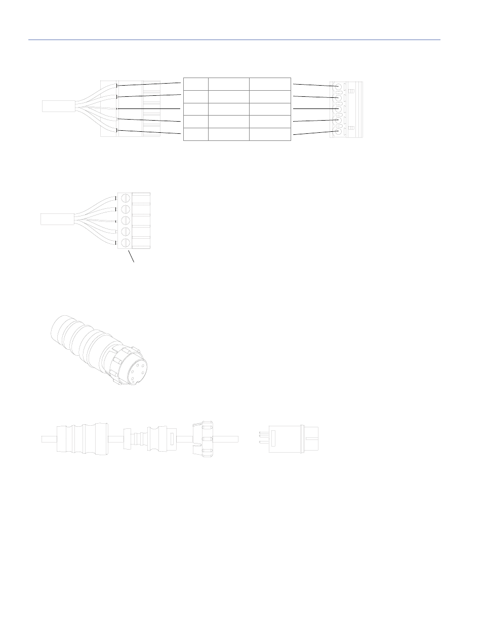
APPENDIX C: PHOENIX AND EN3 CABLE ASSEMBLY
46
2. Insert the five exposed conductors into the five cable holes in the Phoenix connector using the following wiring scheme.
3. Secure the conductors by tightening the five screws in the Phoenix conductor.
4. Disassemble the EN3 5-pin female connector and feed one end of the cable through the boot, cable clamp housing, and
coupling ring.
5. If the EN3 end of the cable has not been stripped, strip the outer shielding 1” and then strip the black, red, blue, and
white wires .275”.
Phoenix 5-Pin Female Cable Mount Connector
Disassembled EN3 5-Pin Female Cable Mount Connector
Pin #1
Black
48 V DC (–)
Pin #2
Red
48 V DC (+)
Pin #3
Unshielded
Audio shield
Pin #4
Blue
Audio (–)
Pin #5
White
Audio (+)
Connector side up
Side (cable attached)
Tighten screws
Cable clamp
housing
Boot
Coupling ring
Cord connector