Marathon technologies corporation 7, Sample bladecenter network adapter switchbay map – Marathon Computer FTvirtual Server User Manual
Page 13
Marathon Technologies Corporation
7
FIGURE 1.
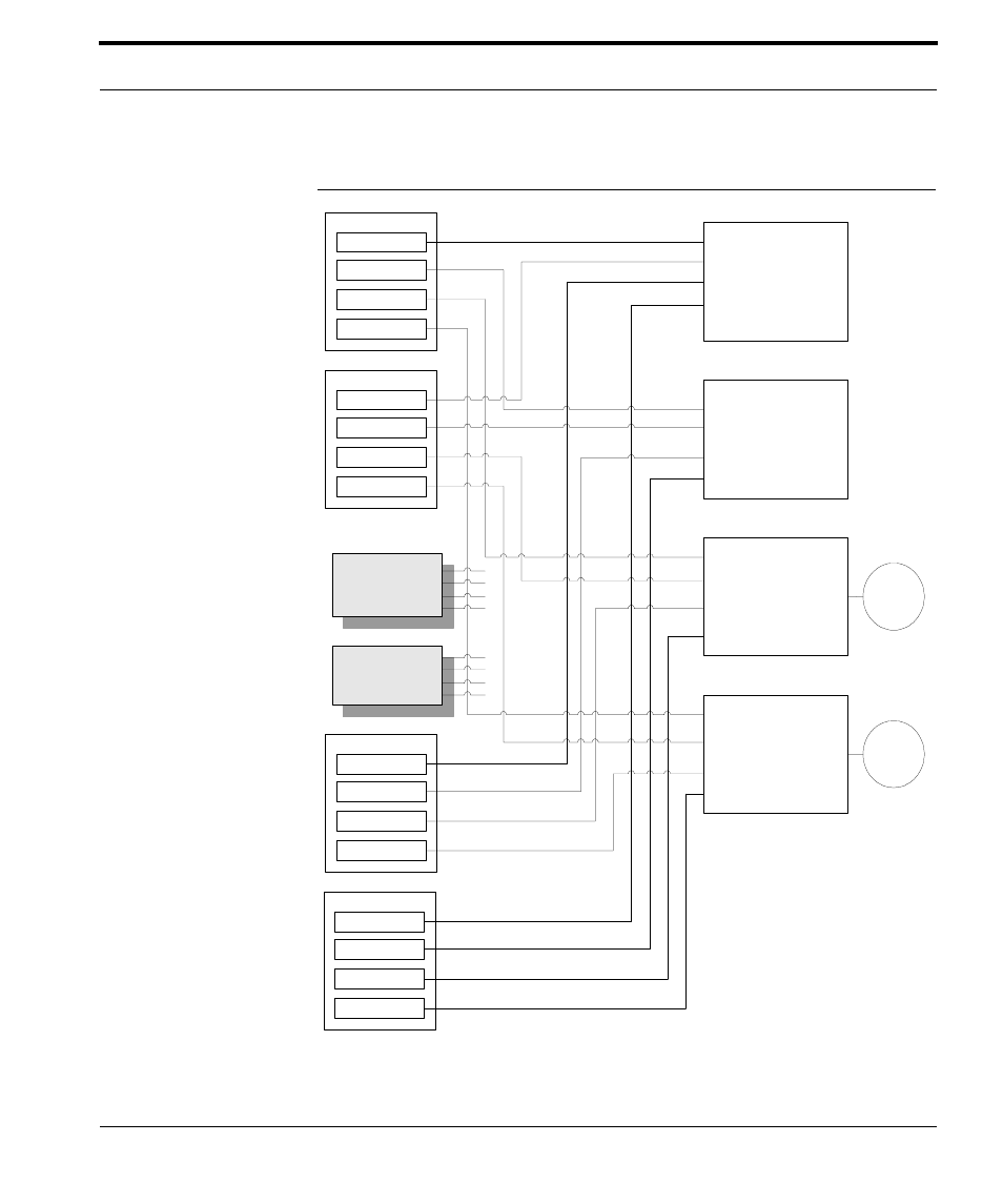
FTv1 CoServer 1
PCI 1:0:0 NIC
Switch Bay 1
CSLink 1 connections only
No external connections
PCI 1:0:1 NIC
PCI 2:2:1 NIC
PCI 2:2:0 NIC
Switch Bay 2
CSLink 2 connections only
No external connections
Switch Bay 3
Redirected for CoServer 1
Management for CoServer 2
Switch Bay 4
Redirected for CoServer 2
Management for CoServer 1
FTv1 CoServer 2
PCI 1:0:0 NIC
PCI 1:0:1 NIC
PCI 2:2:1 NIC
PCI 2:2:0 NIC
FTv3 CoServer 2
PCI 1:0:0 NIC
PCI 1:0:1 NIC
PCI 2:2:1 NIC
PCI 2:2:0 NIC
FTv3 CoServer 1
PCI 1:0:0 NIC
PCI 1:0:1 NIC
PCI 2:2:1 NIC
PCI 2:2:0 NIC
To
Network
To
Network
Blade Bays 1, 5, 9 are assumed to contain CoServer 1
Blade Bays 3, 7, 11 are assumed to contain CoServer 2
Blade Bay pairs 1 & 3, 5 & 7, 9 & 11 each make an Endurance system
FTv2 CoServer 1
FTv2 CoServer 2
Sample BladeCenter Network Adapter Switchbay Map