Metrologic Instruments MS7220 User Manual
Page 43
40
S
CANNER AND
C
ABLE
T
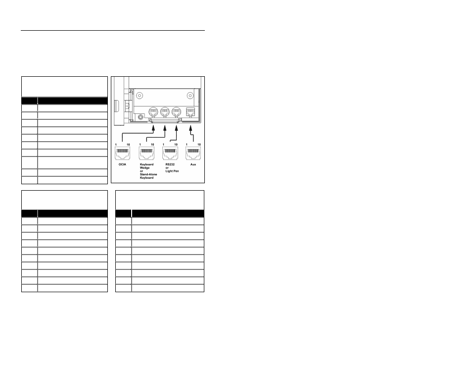
ERMINATIONS
Scanner Pinout Connections
The MS7220 scanner interfaces terminate to 10-pin modular jacks located
on the back of the unit. The serial # label indicates the interface enabled
when the scanner is shipped from the factory.
MS7220-12
OCIA
Pin
Function
1
Ground
2
RS-232 Transmit Output
3
RS-232 Receive Input
4
RDATA
5
RDATA Return
6
Clock in
7
Clock out
8
Clock in Return/Clock out
Rtrn
9
+5VDC
10
Shield Ground
MS7220-12 Keyboard Wedge
or
Stand-Keyboard
MS7220-12
RS-232 or Light Pen
Pin
Function
Pin
Function
1
Ground
1
Ground
2
RS-232 Transmit Output
2
RS-232 Transmit Output
3
RS-232 Receive Input
3
RS-232 Receive Input
4
PC Data
4
RTS Output
5
PC Clock
5
CTS Input
6
KB Clock
6
DTR Input/LTPN Source
7
PC +5V
7
Reserved
8
KB Data
8
LTPN Data
9
+5VDC
9
+5VDC
10
Shield Ground
10
Shield Ground
Continued next page