Middleby Cooking Systems Group Gas Fired PS540G User Manual
Parts manual, Ps540g series gas fired, Table of contents: page 2
PS540G SERIES GAS FIRED:
SPL100505-PF-BD
October 5, 2005
Table of Contents: Page 2
www.middleby.com
email: [email protected]
1-847-741-3300 fax 1-847-741-4406 (Parts Department)
Serial # Code
First 4 digits - order of production
Fifth digit - model specific
Sixth and Seventh digit - month of production
Eighth and Ninth digit - year of production
Parts Manual
for domestic and standard export ovens
A MIDDLEBY COMPANY
Starting Serial # 000160104 & after
©2005 Middleby Marshall Inc.
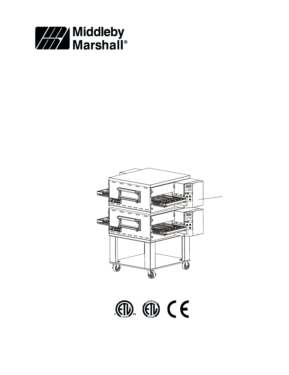
PS540G-Double-
Shown with “New
Style” Front Window
Assembly.
Serial Tag Location
with Wiring Diagrams
Table of contents
Document Outline
- Table of Contents
- Spec Sheet
- Oven and Electrical Specifications
- Key Parts
- View of Oven Panels, Window and Legs (Earlier Production)
- Parts for Oven Panels, Window and Legs (Earlier Production)
- View of Oven Panels, Window and Legs (Later Production)
- Parts for Oven Panels, Window and Legs (Later Production)
- View of Right-hand Control Compartment
- Parts for Right-hand Control Compartment
- View of Blower Area
- Parts for Blower Area
- View of Blower/Motor Compartment
- Parts for Blower/Motor Compartment
- View of Gas Burner & Piping
- Parts for Gas Burner & Piping
- View of “Single” Belt Conveyor
- Parts for “Single” Belt Conveyor
- View of “Split” Belt Conveyor
- Parts for “Split” Belt Conveyor
- PS540G Oven Installation Kit
- PS540G Single Oven Option Base Kit
- PS540G Double Oven Option Base Kit
- PS540G Triple Oven Option Base Kit (Outriggers)
- Standard Finger Configuration
- Wiring Diagram, 208-240 volt 50/60 Hz, 1 Phase 3W 50141 Rev. F2 US/UK/CANADA
- Ladder Wiring Diagram, 208-240 volt 50/60 Hz, 1 Phase 3W 50141 Rev. F1 US/UK/CANADA
- Wiring Diagram, 208-240 volt 50/60 Hz, 1 Phase 3W 52059 Rev. D DN
- Wiring Diagram, 208-240 volt 50/60 Hz, 1 Phase 3W 52065 Rev. D DUT
- Wiring Diagram, 208-240 volt 50/60 Hz, 1 Phase 3W 52053 Rev. D FR
- Wiring Diagram, 208-240 volt 50/60 Hz, 1 Phase 3W 52055 Rev. D GM
- Wiring Diagram, 208-240 volt 50/60 Hz, 1 Phase 3W 52067 Rev. D GK
- Wiring Diagram, 208-240 volt 50/60 Hz, 1 Phase 3W 52061 Rev. D IT
- Wiring Diagram, 208-240 volt 50/60 Hz, 1 Phase 3W 52057 Rev. D SP
- Wiring Diagram, 208-240 volt 50/60 Hz, 1 Phase 3W 52063 Rev. D SW