Chapter 6 chassis maintenance, Hot-swappable” power supply – Mobility Electronics PCI Expansion System P13RR-TEL User Manual
Page 33
M A G M A
Chapter 6 Chassis Maintenance 25
Chapter 6 Chassis Maintenance
Like all computer systems, you will need to perform some routine
maintenance tasks. Some of these include making sure that the air
vents in the chassis are clear of obstructions and that the cooling air
from the fans flows freely. You will also need to check the foam filter
behind the front panel to ensure it is clean, thus allowing for unrestricted
air flow to the fans. You should always keep an eye on all cables to
make sure they are not damaged and are securely connected.
Occasionally, you should remove the chassis cover and check for loose
cards, and remove any dust build-up.
Always to remember to power down your computer and then the
expansion system BEFORE you attempt to perform any maintenance
tasks.
In spite of regular performance of routine maintenance tasks, some
computer systems can experience hardware failures. Fortunately, your
investment in a P13RR-TEL provides you with the ability to easily repair
the system in the event of component failure.
Two of these components are field-replaceable: the cooling fans and
the hot-swappable redundant power supply modules.
“Hot-Swappable” Power Supply
The redundant power supply includes two
hot-swappable modules that share the
power load requirements during normal
operations. Should one module fail for any
reason, the power load will be shifted to the
other module and sound an audible alarm.
If a power supply fails, the monitor will
display a message in the display window,
sound an alarm, update the web-access-
page, and, if you have configured the
SNMP monitoring for email alerts, it will
also send you an email advising you of the
power failure.
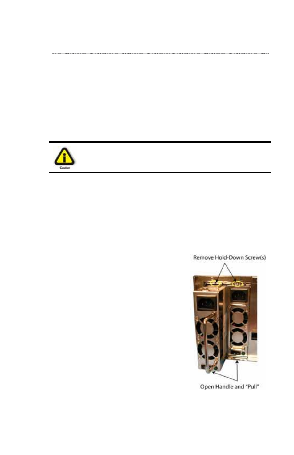
To replace a failed power supply, simply
remove the Phillips-head screw above the
failed power supply module, grab the
handle, and pull. Replace the failed module with a new one and turn on
the power to the module using the power switch at the bottom of the