Warning, El150ex, Pressurized and atmospheric systems – Murphy EL150EX User Manual
Page 2: Important, Installation
L-7758N page 2 of 4
4-13/16 in.
(122 mm)
3-25/32 in.
(96 mm)
4-1/2 in.
(114 mm)
Mounting Holes
1/2 NPT
1/2 NPT
Back Connect
1/4 NPT
2-3/4 in.
(70 mm)
9/32 in. (7 mm)
diameter holes
2 places
Mounting
Ears (2)
Test
Knob
5-9/16 in.
(141 mm)
4-11/16 in.
(119 mm)
5-1/2 in.
(140 mm)
Mounting Holes
1/2 NPT
1/2 NPT
Back Connect
6 in.
(152 mm)
1/2 NPT
Connection
1/2 NPT
3-3/8 in.
(86 mm)
5/16 in. (8 mm)
diameter holes
2 places
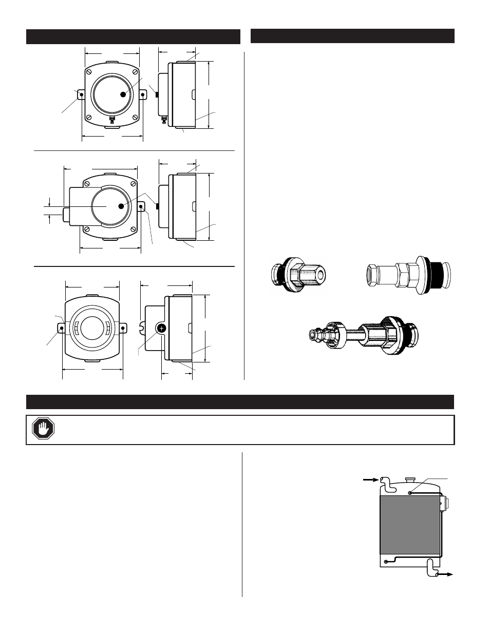
DIMENSIONS
PS FITTINGS INSTALLATION
LEVEL SWICHGAGE
®
INSTALLATION
WARNING:
Perform all installations with the power source “OFF”. Be sure engine and radiator have
cooled and coolant pressure has been relieved. SEVERE BURNS can result. Never remove radiator cap on a hot
A Murphy PS fitting is used when there is no threaded fitting in the top
tank of the radiator to attach tubing for the L150/EL150 series level
SWICHGAGE
®
.
• P/N 15-00-0107 (PS) Accepts 1/4 in. (6 mm) O.D. copper tubing.
• P/N 15-01-0167 (PS Barbed) Barbed fitting accepts 1/4 in.
(6 mm) I.D. flexible tubing and hose clamp.
• P/N 15-01-0202 (PS-D) Accepts 1/2 in. (13 mm) I.D. hose;
1/4 in. (6 mm) copper tube.
1. Determine the entry point into the radiator top tank. See Level
SWICHGAGE
®
Installation for proper location. Drill 5/8 in. (16 mm)
diameter hole in top tank of radiator. Be sure chips do not fall inside
the tank. Remove any burrs on the hole wall.
2. Insert the rubber grommet of the PS Blind Hole Fitting. Tighten the
jam nut while holding the fitting from turning in the hole. The jam
nut will pull the tapered grommet into the hole from the inside of the
top tank causing the grommet to expand and seal the hole.
3. Attach the appropriate tubing or hose for the PS Fitting.
EL150EX
15-00-0107
15-01-0167
15-01-0202
L150
EL150K1
IMPORTANT:
Operation of the L150/EL150K1 is different for a
pressurized cooling system than for an atmospheric (non-pressurized)
system. Installation of the L150/EL150K1 is only slightly different for each
system. Connection of the top tube connection is the major difference.
Differences will be noted in the installation instructions.
Installation Notes
1. All top radiator connections must be away from the return hose
turbulence.
2. All bottom radiator connections must be away from the suction hose.
3. The L150/EL150K1 must be attached to a mounting plate on the radiator
or other framework.
CAUTION:
If the L150/EL150K1 is NOT attached to the radiator, use
high temperature quality flexible hose for the top and bottom connections
to maintain the shock mounting protection for the radiator.
Pressurized and Atmospheric Systems
1. Drain the cooling system.
2. For a PRESSURIZED COOLING
SYSTEM (Figure 1) the shutdown
point is determined by the entry point
A of the tube connection into the top
tank. The engine will shutdown when
coolant level drops below this
connection (see step 4).
If the radiator has a SHALLOW
UPPER TANK, you can make entry
from the top as illustrated in Figure 2.
Insert the copper tube until it is slightly
above the core. Secure the fitting.
4-13/16 in.
(122 mm)
4-15/16 in.
(125 mm)
4-1/2 in.
(114 mm)
Mounting Holes
1/2 NPT
1/2 NPT
Back Connect
1/4 NPT
2-3/4 in.
(70 mm)
9/32 in. (7 mm)
diameter holes
2 places
11/16 in.
(17 mm)
Test
Knob
A
Figure 1: Pressurized System