Product overview, Features, Electrical specifications – Marshall electronic V-R72P-2HDSDI User Manual
Page 2: Mechanical specifications, Operational setup, Connectors, Analog and digital screen formats and frame rates
• HDSDI (SMPTE292M/296M) With reclocked and shaped output
• SDI (SMPTE259M) (ITR-U601) With reclocked and shaped output
Remote control options (Available Summer 2005)
• Small Footprint – occupies only 3RU of a standard EIA 19 inch rack
• Ready to mount – all brackets are factory installed
• Lightweight – 75% lighter than CRT models
• All adjustments and selections are readily available. No menus!
• Settings memory restores active state with power off/on cycle
• Easy to use front panel selection of inputs
• NTSC or Pal operation with automatic signal format detection
• All inputs automatically terminate
• Built in color bar generator for each display
• Includes V-PS12-5V-1 Universal power supply (U.L. class 2)
• Three LEDs (Red, Green, Amber) produce 7 different tally indications
• Unique 180 degree tilt adjustment
• Dry erase label for each screen
1
Product Overview
The Rack mounted and tiltable V-R72P-2HDSDI represents leading edge technology in LCD imaging for broadcast and
professional video applications featuring High Resolution, megapixel, TFT screens with completely digital signal processing.
All SMPTE/ITU digital video standards and signal types are accepted and displayed on each screen of this model. All video
formats are scaled to fi t on screen in the highest resolution using a state of the art LSI that incorporates 4x4 pixel interpola-
tions with precision Gamma correction to produce the best images available.
2
Features
Analog and Digital Screen Formats and Frame Rates
All signal types and frame rates are automatically detected
• 525 –60i / 625 - 50i (Interlaced NTSC/PAL)
• 720 x 486P (Progressive)
• 720 x 576P (Progressive)
• 720 x 1280 – Analog-50P, 59.94P, 60P /Digital 23.97P, 24P, 25P, 50P, 59.94P, 60P (Progressive)
• 1035 x 1920 - 59.94i, 60i (Interlaced)
• 1080 x 1920 – 50i, 59.94i, 60i / 23.973Psf, 24Psf, 25Psf, 29.97Psf, 30Psf
Psf=Progressive or Segmented Frame formats
V-PS12-5V-1
Universal power supply
(U.L. class 2)
3 RU
5.14”
13.5 cm
3
Electrical Specifications
Number of Screens
2
Screen Aspect
16:9 / 4:3 switchable
Display (Viewing Area)
7” (6.14”H × 3.27”V) (156.0mm x 83.28mm)
Viewing Angles
130 ̊ H x 120 ̊ V
Resolution (Dots)
800H×RGBx480V (1.2 million pixels)
Dot Pitch
0.065 mm (W) x 0.175 (H)
Pixel Response
<30ms
Contrast Ratio
400:1
Brightness (in cd/m²)
380 cd/m²
System
Digital
Inputs per display
HDSDI/SDI with re-clocked output (BNC)
Outputs per display
Active Composite loop through BNC
Reclocked SDI loop through BNC
Color Bar Signal
Full field SMPTE
Power required
12 V D.C. from external U.L. Class 2 power supply (included) max 5.0 AMP
Power Consumption
24 Watt Nominal
Operating temperature
32 ̊ F to 110 ̊ F (0 ̊ C to 45 ̊ C)
2
3
V-R72P-2HDSDI
V-R72P-2HDSDI
Users Guide
Users Guide
Marshall Electronics
Dimensions
19.125”W x 2.5”D x 5.14”H (48.5cm x 6.35cm x 13.5cm)
V-R72P-2HD Weight
3.0lbs (2.27kg)
V-PS12-5V-1 Power Supply Weight
1 lbs (0.45kg)
4
Mechanical Specifications
5
Operational Setup
1. Unpack the V-R72P-2HDSDI and accompanying V-PS12-5V-1 power supply. Physically inspect for any damage that may
have occurred during shipping. Should there be any damage, immediately contact Marshall Electronics at 800-800-6608. If
you are not located within the continental united states call +1 310-333-0606.
2. After inspection, install in your desired location of a standard EIA 19-inch equipment rack. Adequate ventilation is required
when installed to prevent possible damage to the V-R72P-2HDSDI internal components.
3. Connect required cables for signal input and output.
Please note that power must be applied to the V-R72P-2HDSDI for all outputs to be activated.
All BNC connectors should be rated for 75Ω.
4. Plug the V-PS12-5V-1 power supply into the A.C. source
5. Attach twist lock power connection from V-PS12-5V-1 power supply to the back of the unit.
6. Turn on the V-R72P-2HDSDI by depressing the power switch located on the front of the unit.
6
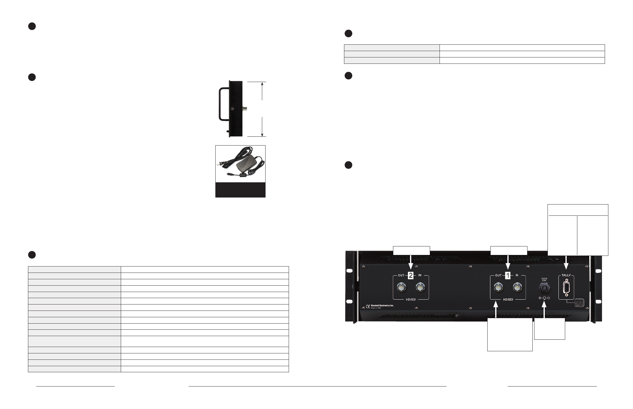
Connectors
* SDI inputs comply to SMPTE259M / ITU-R BT601
* HDSDI inputs comply to SMPTE292M,294M
* Active Outputs Require Power to be applied for activation
* Tally lamps active when connected to ground
Monitor 2
HDSDI or SDI In
12 VDC from
V-PS12-5V-1
power supply
Left Pin - Pos
Right Pin- Neg
Active Outputs require power
to be aaplied
All input signals appear as
output signal
HDSDI/SDI signals are
reshaped and re-clocked
Analog output signals are
buffered and amplifi ed
Monitor 1
HDSDI or SDI In
Pin1-M
1Grn
Pin2-M
1Red
Pin3-M
1Yel
Pin4-
Gnd
Pin5-Gnd
Pin6-
Pin7-
Pin8-
Pin9-
Pin10-
Pin11-M
2Grn
Pin12-M
2Red
Pin13-M
2Yel
Pin14-
Gnd
Pin15-Gnd
Tally IN
DB-15 Female