Control panel performance data specifications, Subject to change without notice.) – Miller Electric MARKVI User Manual
Page 2
2
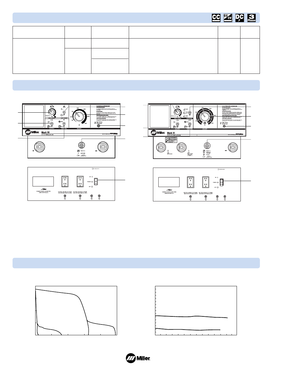
Control Panel
Performance Data
Specifications
(Subject to change without notice.)
DC Amperage/
Voltage Range
20 – 315 A
in CC Mode
10 – 30 V in
CV Mode with
CC/CV Module
Max. Open-Circuit
Voltage (DC)
75 VDC in CC Mode
38 VDC in CV Mode
with CC/CV Module
26 VDC ±2 V
with CC/CV Module
and low OCV
Amps Input at 750 Amps Output, 50/60 Hz
230 V 380 V 400 V 415 V 440 V 460 V 575 V KVA KW
164
97
92
91
84
82.5
66.1
65.2 41.9
Dimensions
H: 65 in
(1651 mm)
W: 56-3/4 in
(1442 mm)
D: 34-1/4 in
(870 mm)
Net
Weight
Mark VI :
1725 lb
(784 kg)
Mark VI-2:
1575 lb
(718 kg)
Rated Welding Output
at 44 Volts DC
Single Module
250 A at 60% Duty Cycle
Main Transformer
60 Hz: 750 A at 100% Duty Cycle
1500 A at 25% Duty Cycle
50 Hz: 750 A at 60% Duty Cycle
1160 A at 25% Duty Cycle
8
7
UPPER PANEL FOR CC UNITS
LOWER PANEL
6
4
5
1
2
3
SINGLE MODULE
VOLTS
30
AMPERES
250
DUTY CYCLE
60%
MAX OCV
75 VDC
TOTAL MACHINE
60Hz - 750 Amps @ 100% Duty Cycle
50Hz - 750 Amps @ 60% Duty Cycle
6
8
4
5
7
1
2
3
UPPER PANEL FOR CC/CV UNITS
LOWER PANEL
SINGLE MODULE
VOLTS
30
AMPERES
250
DUTY CYCLE
60%
MAX OCV
75 VDC
TOTAL MACHINE
60Hz - 750 Amps @ 100% Duty Cycle
50Hz - 750 Amps @ 60% Duty Cycle
1. Arc Force Control
2. Remote/On Output Contactor Control
3. Remote/Panel Output Amperage Control
4. Hot Start On/Off Switch
5. Amperage Adjustment Control
6. High-Temperature Shut Off Indicator
7. 14-Pin Remote Receptacle
8. Power On/Off Switch
1. Arc Force Control
2. Remote/On Output Contactor Control
3. Remote/Panel Output Amperage Control
4. Process Selector
5. Amperage/Voltage Adjustment Control
6. High-Temperature Shut Off Indicator
7. 14-Pin Remote Receptacle
8. Power On/Off Switch
CC VOLT/AMP CURVES
FOR EACH MODULE
DC VOL
TS
DC AMPS
80
60
40
20
0
0
100
200
300
400
500
CV VOLT/AMP CURVES
FOR EACH MODULE
VOL
TS
AMPS
80
70
60
50
40
30
20
10
0
0
100
200
300
400
500
600
700