Meridian America DSP420 User Manual
Page 6
CAUTION
RISK OF E
LECTRIC S
HOCK
DO NOT O
PEN
AVIS: RISQ
UE DE CH
OC ELECT
RIQUE - N
E PAS OUV
RIR
REFER TO
IMPORTA
NT SAFET
Y
INSTRUCT
IONS BEF
ORE
INSTALLA
TION
~100-240V 50-60Hz
OUTLET S
UITABLE F
OR LOADS
UP TO 10
00W 10A
MAXIMUM
100-120V
~
or
1000VA 5
A MAXIM
UM
for 220-24
0V
~
❸
❹
❼
❽
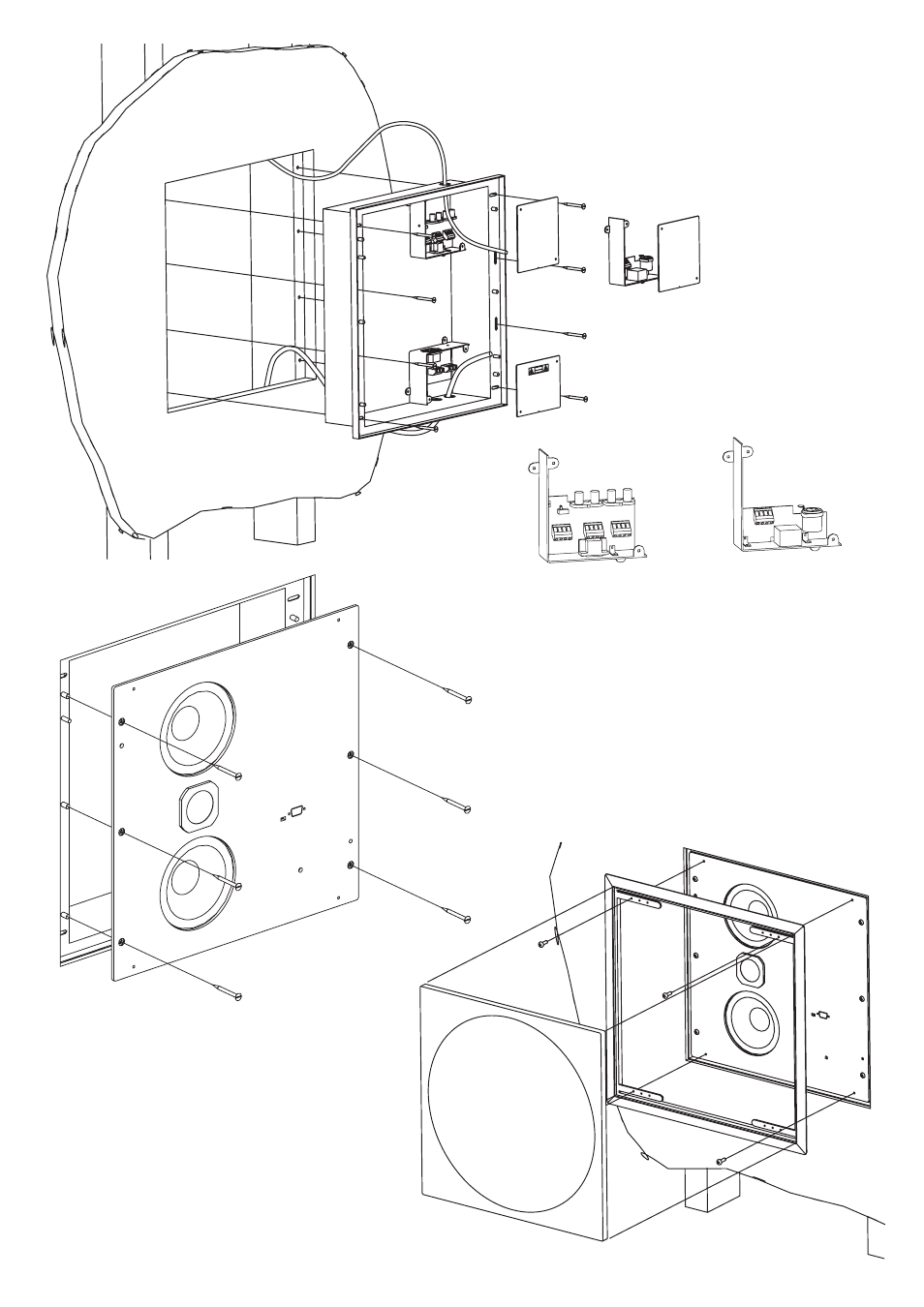
Step 3: Fix back-box into cut-out.
Thread cables through correct holes
in back box: audio/comms cables
come in from the top; power from the
bottom (see separate sheet for power
wiring installation instructions).
Step 4: Fix the required audio junction
box in top right position. The digital
board (left) is already installed; the
analogue board (right) is supplied loose.
You can use either the connectors or the
terminal blocks provided.
Step 7: Neatly position power
and comm cables and push the
loudspeaker unit all the way in so
that it locates on the pegs in the
back-box. Secure using the six M5
x 12 button-head socket screws
supplied, Meridian part number
H61513.
Step 8: Secure frame and fit grille.
Grille can be carefully removed using the
extraction tools supplied.