Vx-1 stereo program equalizer, Operating instructions – Meyer Sound VX-1 User Manual
Page 3
VX-1
Stereo
Program
Equalizer
Operating Instructions
Meyer Sound Laboratories, Inc.
2832 San Pablo Avenue
Berkeley, CA 94702
Power
EQ
Mono
G a i n
VX-1 Program Equalizer
-12
-6
-3
0 dB
+3
+6
1 k
490
320
240
175
110
60
-12
-6
-3
0 dB
+3
+6
-12
-6
-3
0 dB
+3
+6
17 k
9 k
6 k
4 k
3 k
2 k
1 k
Low
Mid
High
Channel B
∞
0 dB
+2
+3
+4
+5
+6
-3
-6
-12
-24
-
-12
-6
-3
0 dB
+3
+6
1 k
490
320
240
175
110
60
-12
-6
-3
0 dB
+3
+6
-12
-6
-3
0 dB
+3
+6
17 k
9 k
6 k
4 k
3 k
2 k
1 k
Low
Mid
High
Channel A
Figure 3. VX-1 Front Panel Controls
EQ In/Out Switch
The EQ In/Out Switch engages (in) or bypasses (out) the
VX-1 equalization stages. When the equalization is engaged,
the LED lights and the equalization controls are active.
When the equalization is bypassed, only the Master
Gain control and Mono switch are active.
Master Gain Control
The Master Gain Control regulates the gain of the VX-1. Its
range is from off to +6 dB, with 0 dB (unity) gain at the center
position.
Mono Switch
When the Mono Switch is engaged (in), the LED lights and
the two input channels are summed and routed to both out-
puts with equal amplitude. When the Mono switch is
disengaged (out), the VX-1 operates in stereo.
Signal/Clip Indicators
Centered directly under the equalization controls for each
channel, the Signal/Clip indicators will flicker green when
Equalization Controls
The VX-1 features a unique, Virtual Crossover™ implemen-
tation which is well suited for tailoring the broadband re-
sponse of program material. Operationally, it may be likened
to a conventional active loudspeaker crossover.
Each channel of equalization incorporates five controls: two
frequency breakpoint controls, and three band gain controls.
The left-hand frequency control regulates the frequency
breakpoint between the Low and Mid bands, while the right-
hand frequency control regulates the breakpoint between the
Mid and High bands. The gain controls affect the
relative amplitude (boost or cut) within each frequency
band, with a range of -12 to +6 dB.
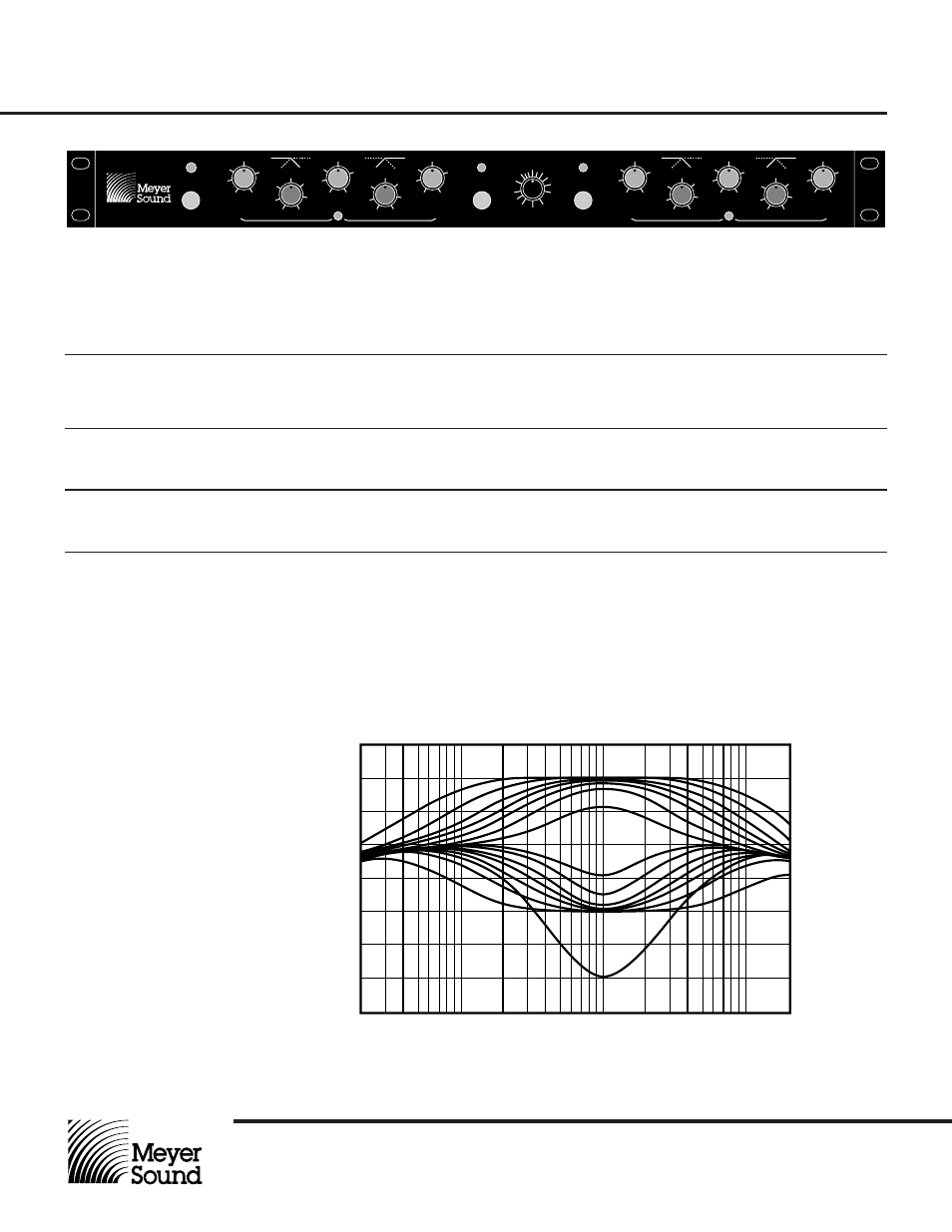
The VX-1 equalization sections are first-order (6 dB/
octave) minimum-phase networks that provide gentle,
natural sonic characteristics. Figure 4 illustrates
typical response curves for various midrange control
settings.
their corresponding channels are passing audio. The
indicators flash red to register signal clipping.
0.0
+3.0
+6.0
-9.0
-6.0
-3.0
-12.0
20
100
1k
10k
20k
Gain in dB
Frequency in Hz
Figure 4. VX-1 Response at Various Midrange Settings