Scanner and cable terminations, Scanner pinout connections – Metrologic Instruments MS3780 User Manual
Page 40
36
S
CANNER
AND
C
ABLE
T
ERMINATIONS
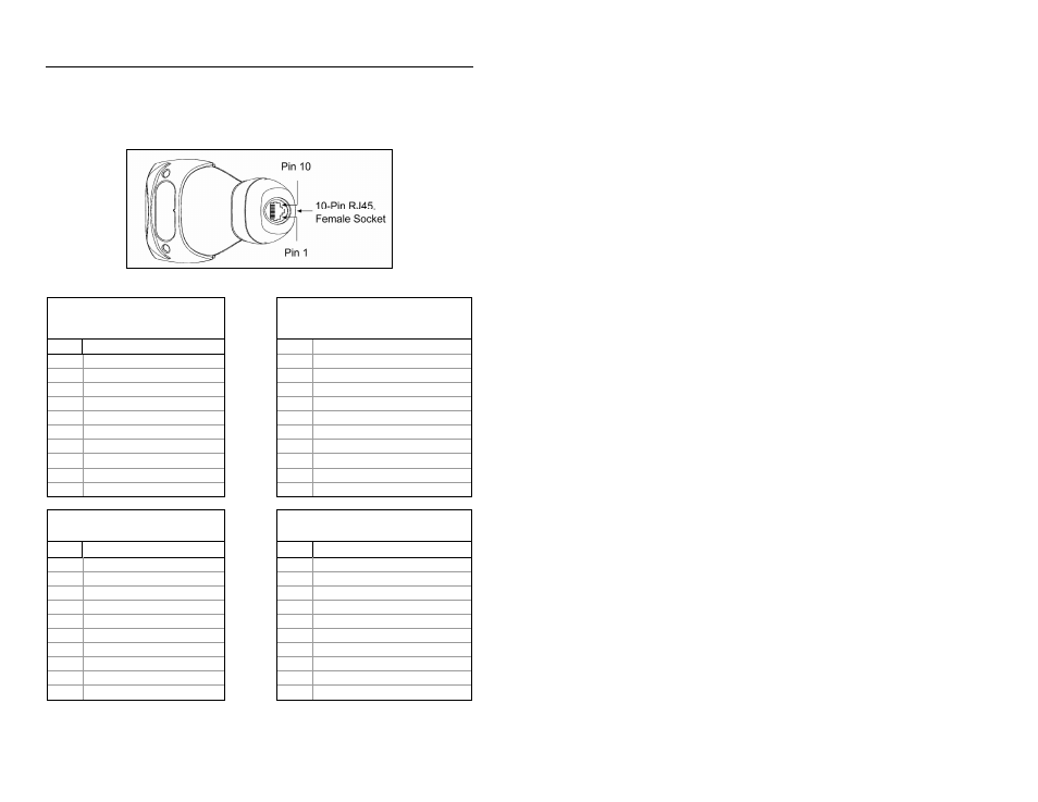
Scanner Pinout Connections
The MS3780 scanner interfaces terminate to a 10-pin modular socket.
The serial # label indicates the interface enabled when the scanner is shipped
from the factory.
Figure 25.
Keyboard Wedge and
Stand-Alone Keyboard
MS3780-47
RS232 and Light Pen Emulation
MS3780-41
Pin Function
Pin Function
1 Ground
1 Ground
2
RS232 Transmit Output
2
RS232 Transmit Output
3
RS232 Receive Input
3
RS232 Receive Input
4 PC
Data
4 RTS
Output
5 PC
Clock
5 CTS
Input
6
KB Clock
6
DTR Input/LTPN Source
7 PC
+5V
7 Reserved
8 KB
Data
8 LTPN
Data
9 +5VDC
9 +5VDC
10 Shield
Ground
10 Shield
Ground
MS3780-40 Full Speed USB
RS232 Low Speed USB MS3780-38
Pin Function
Pin Function
1 Ground/USB-
1 Ground/USB-
2
RS232 Transmit Output
2
RS232 Transmit Output
3
RS232 Receive Input
3
RS232 Receive Input
4 RTS
Output
4 RTS
Output
5 CTS
Input
5 CTS
Input
6 D+
6 D+
7 USB
+V
7 USB
+V
8 D-
8 D-
9 +5VDC
9 +5VDC
10 Shield
Ground
10 Shield
Ground
Continued on next page.