Wattage, Caution, Figure 1 – Marley Engineered Products B User Manual
Page 2: Figure 2 wiring diagram figure 3 clip’n’fit, Board
NOTE: Lead holes for a #8 sheet metal screw have been provided in the sides
of the back box. After the finished wall or ceiling has been put up, drive a #8(m4)
sheet metal screw (recommended 1”(25mm) long) through the side of the box
not mounted to the stud.(joist) This will prevent the back from pulling out when
installing the heater assembly. (See Figure 1)
NOTE: Heaters are factory wired per nameplate, voltage and wattage. Refer to
Table1, page 3 for details. See “TO CHANGE WATTAGE OUTPUT” section if
lower wattage is desired and make change before installating heat deck.
INSTALLATION AND WIRING
OF HEATER / FAN ASSEMBLY
1.
Following wiring diagram (Figure 2) connect supply wires to heater lead-
wires in back box using appropriate wire connectors.
NOTE: For 120 volt heaters connect the white neutral supply lead to the heater’s white
or red with white flag marker pigtail lead, and connect the black supply lead to the black
pigtail lead.
2.
Secure supply ground wire under green ground screw in back box (or
green ground wire if provided).
3.
Fit heater/fan assembly into back box making sure all wiring is powitioned
away from fan and heating element.and secure in place with (2) screws
provided through the center slots in the sides of the fan assembly.
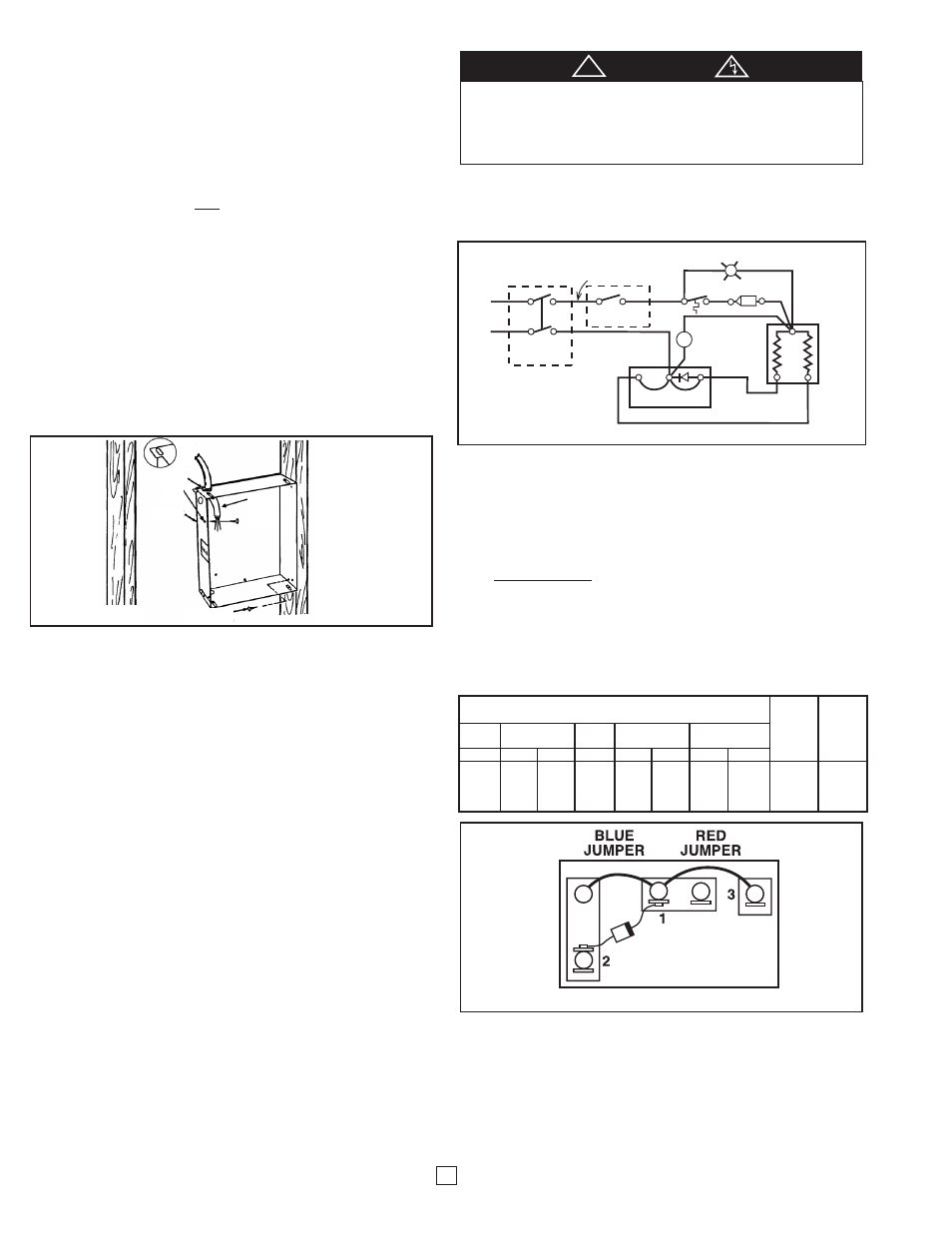
TO CHANGE WATTAGE OUTPUT
The chart below shows the wattages available by model. Each heater is facto-
ry wired for its maximum wattage. The last two columns in the chart refer to the
jumpers on the CLIP’n’FIT
®
Board. To change wattage, clip out jumper 1 and/or
jumper 2 as shown in the chart below. Completely remove jumpers by clipping
at both ends as close to the board as possible.
GENERAL
Wall Mounted
•The C series heaters are designed for recessed installation in 2 X 4 stud or
larger wall using the model CBB (Type CO2-BB) back box. The heater may
be wired using standard building (60 degrees C minimum) wire.
•The optimum mounting height for this heater is 18” to 24” (457mm to
610mm) from floor to bottom of back box. In any case, do not install closer
than 4.5” (114mm) from the floor or adjacent wall.
Ceiling Mount
•The C Series heaters are designed for ceiling mount provided the wattage
does not exceed 1000 watts. In order for your heater to be rated for
ceiling application, the heater must be trimmed back to 1000 watts or less.
(See Change Wattage Output below)
•The optimum clearances to any wall surface are 12 inches. Do not mount
heater in the ceiling if these clearances are not met.
•Ceiling heaters can be recessed or surfaced mounted.
Heaters are also approved for semi-recessed or surface mounting on walls. Refer to
instructions for installations of the CSM Surface Mounting frame.
INSTALLATION OF BACK BOX
IN NEW CONSTRUCTION
NOTE:
If the finished wall surface is already up, follow instructions for
“INSTALLATION OF BACK BOX IN EXISTING CONSTRUCTION”.
1.
Allow for the thickness of the finished surface when installing the back
box. The edge of the back box must be installed flush with the finished
surface. Markings on the side of the back box for 1/2” or 5/8” finishing
wall are provided.
2.
Determine which side of the back box is to be mounted against a stud or
joist and bend the tabs at the rear corners out 90 degrees so that the
back box will be square with the stud after installation.
3.
Remove one of the knockouts on left side of the back box and install a
cable or conduit connector. (See warning 13)
4.
Position back box against side with studs or ceiling joist and secure with
nails or screws as shown in Figure 1.
NOTE: The back box must be installed to a wall stud or ceiling joist and
secured using nails or screws as shown in Figure 1.
5.
Run power supply cable through the connector, leaving about 6” of wire
inside the box.
6.
Connect the supply cable ground wire to green ground wire provided.
NOTE: Lead holes for a #8 sheet metal screw have been provided in the sides
of the back box. After the finished wall or ceiling has been put up, drive a
#8(m4) sheet metal screw (recommended 1”(25mm) long) through the side of
the box not mounted to the stud. This will prevent the back box from pulling
out when installing the heater assembly. (See Figure1)
INSTALLATION OF BACK BOX
IN EXISTING CONSTRUCTION
1. The edge of the back box must be installed flush with the finished surface.
Determine which side of the back box is to be mounted against a stud or joist
and bend the tabs at the rear corners out 90 degrees so that the back
box will be square with the stud after installation. (See Figure 1).
2. Carefully cut a hole measuring 9-3/8”(239mm) wide by 11-1/8”(284mm)
long. One edge of the hole must be cut along edge of the wall stud.
3. Bring power supply cable to heater mounting location leaving at least
10”(255mm) of cable for wiring.
4. Remove desired knockout on left side of back box.
5. Install cable clamp to cable and install into back box, leaving at least
6”(152mm) of cable in box for wiring.
6. Connect the supply cable ground wire to green ground wire provided.
7. Fit back box into mounting hole in wall by first inserting cable end of box then
rotating box into position.
8. Secure box to wall stud or ceiling joist using nails or screws.
2
Figure 1
BEND
OUT
TAB
CABLE CLAMP
LEAD
HOLES
BACK BOX
NAILS OR
SCREWS
SUPPLY
WIRING
CABLE
LAMP
R
M
ELEMENT
TCO
LIMIT
CONTROL
MOTOR
CLIP'N'FIT
®
2
1
3
RED
JUMPER
BLUE
JUMPER
REMOTE 1
POLE T'STAT
BLACK
RED
REMOTE OR
OPTIONAL 2
POLE T'STAT
BLACK
RED
L1
L2/N
Figure 2 Wiring Diagram
Figure 3 Clip’n’Fit
®
Board
WATTAGE
C1512IF
C2024IF
C2224IF
Jumper 1
Jumper 2
C1512T2
C1524T2
C2028IF
C2024T2
C2224T2
Blue
Red
@120V @208V @240V @208V
@208V @240V @208V @240V
Jumper
Jumper
1500
1125
1500
2000
1500
2000
1688
2250
Leave In Leave In
1125
844
1125
1500
1125
1500
1266
1688
Clip Out Leave In
750
563
750
1000
750
1000
844
1125
Leave In Clip Out
375
281
375
500
375
500
422
563
Clip Out Clip Out
TO PREVENT POSSIBLE WIRING DAMAGE CUT EXCESS SUPPLY
WIRE INSIDE BACKBOX TO PROVIDE APPROXIMATELY 6 INCHES
FOR CONNECTION TO HEATER LEADS. AFTER CONNECTIONS ARE
MADE, MAKE SURE CONNECTIONS ARE TIGHT AND ALL WIRING IS
POSITIONED AWAY FROM FAN BLADE AND HEATING ELEMENT.
CAUTION
!