Fireplace framing specifications continued, Figure 11, Figure 10 – Miele MNTSVBE User Manual
Page 7: Ebvcl (corner-left), Ebvcr (corner-right)
7
NOTE: DIAGRAMS & ILLUSTRATIONS NOT TO SCALE.
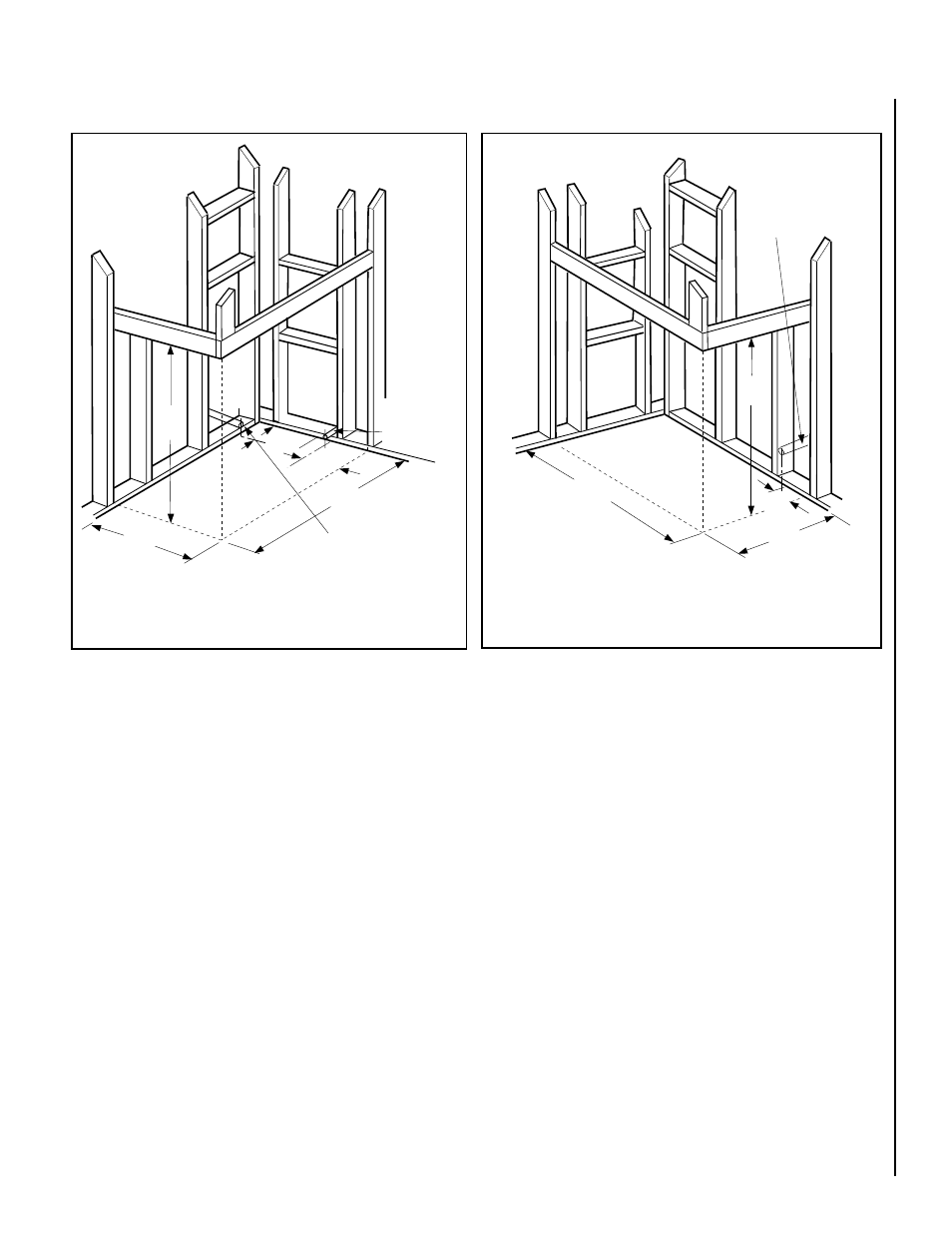
Figure 11
FIREPLACE FRAMING SPECIFICATIONS CONTINUED
Figure 10
*41
¹⁄₂
(1054)
40
¹⁄₈
(1019)
*This dimension can be reduced to 41 inches (1041 mm). This results in 0 in. (0 mm)
clearance between framing and unit framing spacers. (The 41
¹⁄₂ in. dimension permits easier
fireplace installation, if unit is installed after framing is erected.)
24
(610)
EBVCL (Corner-Left)
inches (millimeters)
6
¹⁄₄
(159)
9
³⁄₄
(248)
Optional Gas Line
Location Center of gas line
is 3 in. (76 mm) up from floor.
Gas Line
Center of gas line
is 3 in. (76 mm)
up from floor.
Minimum Framing
Stud size is 2 x 4
*41
¹⁄₂
(1054)
40
¹⁄₈
(1019)
24
(610)
*This dimension can be reduced to 41 inches (1041 mm). This results in 0 in. (0 mm)
clearance between framing and unit framing spacers. (The 41
¹⁄₂ in. dimension
permits easier fireplace installation, if unit is installed after framing is erected.)
EBVCR (Corner-Right)
inches (millimeters)
Gas Line
Center of gas line
is 3 in. (76 mm)
up from floor.
9
⁷⁄₈
(251)
Minimum Framing
Stud size is 2 x 4