Switch settings, Led indicators – Moxa Technologies Moxa CSM 200 User Manual
Page 6
- 6 -
ATTENTION
This is a Class 1 Laser/LED product. Do not stare into the
Laser Beam.
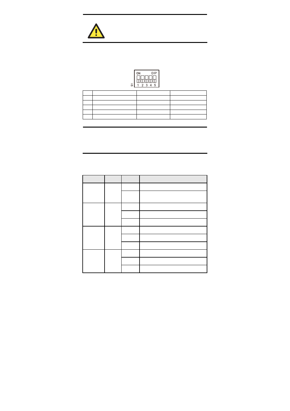
Switch Settings
There is 1 set of DIP switches on the board. The following figure and table
give the settings for the 5-connector DIP switch.
DIP Function
ON
OFF
1
Auto Negotiation
Enable
Disable
2
Force TP Speed
100 M
10 M
3
Force TP Duplex
Full Duplex
Half Duplex
4
Link Fault Pass Through
Enable
Disable
5
Operating Mode
Store-and-Forward
Pass Through
NOTE
1.
All the DIP settings default to “ON”.
2.
When configured for Pass Through mode, the Ethernet port
and fiber port should transmit at 100 Mbps, which is
equivalent to full duplex mode.
LED Indicators
There are 2 LEDs on the front bracket of the CSM-200 slide-in modules.
LED
Color
State
Function
On
Power is being supplied to power input.
PWR Green
Off
Power is not being supplied to power
input.
On
FX port’s 100 Mbps is active.
Blinking
Data is being transmitted at 100 Mbps.
Fiber Link
Green
Off
100BaseFX port is inactive.
On
TP port’s 10 Mbps is active.
Blinking
Data is being transmitted at 10 Mbps.
10M (TP)
Yellow
Off
TP port’s 10 Mbps link is inactive.
On
TP port’s 100 Mbps is active.
Blinking
Data is being transmitted at 100 Mbps.
100M (TP) Green
Off
TP Port’s 100 Mbps is inactive.