Do s dont' s, Nw14/nw35, Mvc1 – M&S Systems MC111M/DM User Manual
Page 3: Nwrc14, Ns3/ns3b, Bd3/d3/bd3b/d3b, Awpm, Aster, Peakers, Atio speakers
M
ASTER
U
NIT
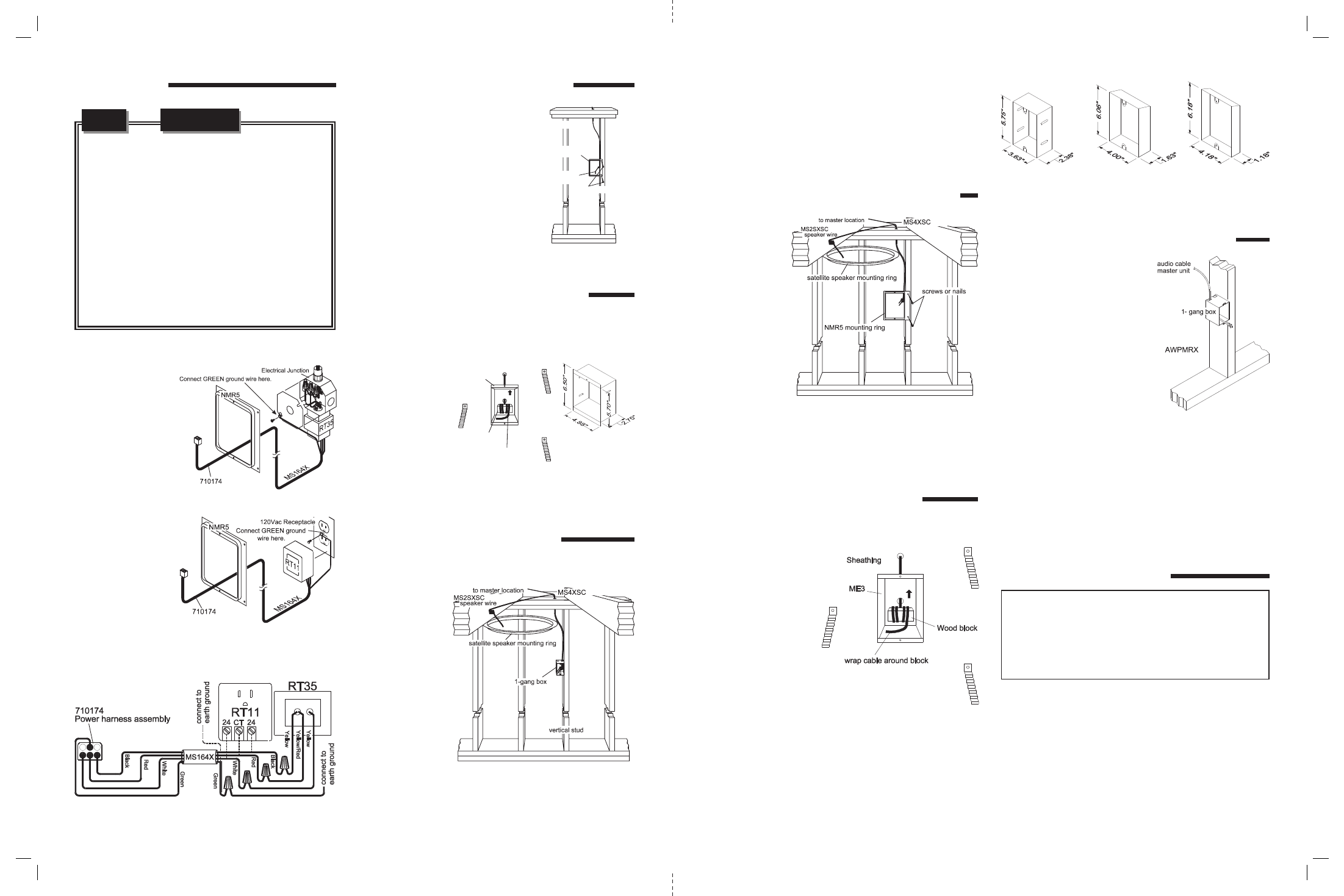
Locate an NMR5 mounting ring for the master unit. Position
the mounting ring approximately 52” high. Have a qualified
electrician run a
d e d i c a t e d
1 2 0 VA C / 6 0 H z
receptacle
with
ground connection
from the power
panel to a remote
junction box in
which to mount the
RT35
power
transformer. Install
and connect the
remote
power
transformer
as
shown in Figure
1 and Figure 2.
Use
Figure
1
and Figure 3 for
plug-in version using
RT11.
S
PEAKERS
N14, N35, N15D
At each room station location, nail or
screw the NMR5 mounting ring (for
N14, N35, N15D or NWRC14) to a
vertical wall stud approximately 52”
above the floor. RETROFIT: locate
mounting rings at least 1” from studs.
From the master unit location, run
MS4XSC cable to each remote station
location. Secure approximately 12” of
wire at the speaker location to protect
wire from dry wall damage. Secure
cables at the master.
P
ATIO SPEAKERS
NW14/NW35
Run a single cable MS4XSC from the master unit location to
each
outdoor
speaker location
and secure the
cable to the correct
plastic or metal
enclosure
by
wrapping the cable
around a small
piece of wood.
Use
NME5
enclosure
for
recessed NW14 or
NW35
patio
stations.
S
ATELLITE
S
PEAKERS USING
MVC1
VOLUME CONTROL
At each room
station location,
nail a single gang
box for the
MVC1 volume
control to a
vertical
stud
approximately
52” above the
f l o o r .
RETROFIT: use
a single gang
box
designed
for
existing
construction.
Careful consideration should be used when determining wall housing
location. DO NOT install wall housing in the following locations
:
☛
DO NOT Install wall housing in return air ducts.
☛
DO NOT install wall housing in exterior walls
☛
DO NOT Install wall housing underneath cabinets or over counter
tops.
☛
DO NOT install wall housing in stud cavities with other 120/240
appliances.
☛
DO NOT install wall housing within 18” of dimmers, fluorescent
light fixtures, security wiring and other control wiring.
☛
DO NOT install wall housing within 2” of room corners.
☛
DO make sure all mounting rings are level and oriented as
shown in these instructions.
DO
s
DONT'
s
&
Generally, existing type single gang boxes will mount between
vertical studs at least 1” from studs. From the master unit wall
housing, run MS4XSC cable to each remote station location.
Secure approximately 12” of wire at the speaker location
to protect wire from dry wall damage. Secure cables at the
master. Note: No more than 2 satellite speakers can be
connected to the MVC1.
R
EMOTE
C
ONTROLS USING
NWRC14
At each room
station location,
nail an NMR5
mounting ring
to a vertical
s
t
u
d
approximately
52” above the
floor. From the
master unit wall
housing,
run
MS4XSC cable
to each remote
station location.
S e c u r e
approximately
12” of wire at the speaker location to protect from dry wall
damage. Secure cables at the master. Note: No more than 2
satellite speakers can be connected to the NWRC14.
D
OOR
S
TATIONS
NS3/NS3B &
BD3/D3/BD3B/D3B
Run MS4DCXSC or
from the master unit
location to each door
station.
Allow
18
inches of excess cable
on each end. On the
door speaker end,
suspend
the
ME3
metal enclosure on
the cable about 50
inches above the floor
(porch) so the brick
mason can flush and
level it in the brick
wall. If wood or
aluminum siding is used, secure surface mount housing SMP3
(for NS3B series) or SME3D (for BD3B/D3B series) to the
finished wall using galvanized screws. Secure cables at master.
E
XTERNAL
M
USIC
S
OURCE
AWPM
External
Music
Sources
(AWPM): Choose a location
for the AWPM that will
be easily accessible to the
sources that are to be
connected to the system
(close to the stereo receiver,
TV or VCR for example). At
this location, attach a single
gang box to a wall stud at a
center height of normal wall
outlets. Make sure the single
gang box extends past the
wall stud and into the room so it will be flush with the
sheetrock when it is applied. Run the Red or Black shielded
audio cable (included in the AWPMRX) from the master unit
location to the AWPM location. Note: Only one cable is
required for use with the MC111M/DM. Secure the audio
cable with a loose knot after it has been pulled through the
single gang box. Secure the cable at the master.
D
OOR
R
ELEASE
O
PTIONS
Door or Gate release mechanism: Run a single line of
VM127X from the master unit location to the door release
mechanism and to each N15D/N35D remote station. Do
not bundle the VM127X wires with the intercom wires! Connect
the Red and White wires to the two wires or terminals of the
door release mechanism. Run another single line of VM127X
from the master unit location to a gang box next to a 120VAC
PRINTER’S INSTRUCTIONS:
INSTR,INSTL,ROUGH-IN,MC111 - LINEAR P/N: 115741 C - INK: BLACK - MATERIAL: 20 LB. MEAD BOND - SIZE: FLAT: 17.000” X 11.000”, FOLDED 8.500” X 11.000” - SCALE: 1-1 - FOLDING: 1-FOLD VERTICAL - SIDE 2 OF 2
Figure 2 - RT35 Power transformer hookup
Figure 3 - RT11 Power transformer hookup
Figure 1 - Power transformer wiring diagram
n
o
i
t
a
c
o
l
r
e
t
s
a
m
o
t
s
w
e
r
c
s
ll
a
w
y
r
d
e
l
b
a
c
d
u
t
s
)
t
u
o
e
d
i
s
d
e
m
r
o
f
(
g
n
i
r
g
n
i
t
n
u
o
m
C
S
X
4
S
M
Figure 4 - Remote
station Rough-in
P
U
k
c
o
l
b
d
n
u
o
r
a
e
r
i
w
p
a
r
w
5
E
M
N
g
n
i
h
t
a
e
h
S
k
c
o
l
b
d
o
o
W
Figure 6 - Recessed patio
speaker mounting
Figure 5 - NME5
recessed enclosure
Figure 7 - Remote station with satellite speaker
Figure 8 - Remote Intercom station with satellite speaker
P
U
Figure 9 - Recessed door station rough-in
Figure 10 - ME3
enclosure for all door
stations
Figure 11 - SME3D
surface mount
enclosure
Figure 12 - SMP3
surface mount
enclosure
Figure 13 - AWPMRX installation
The door release option is a momentary normally open dry
contact closure provided by the master and door release
equipped remote stations and remote controls. This dry
contact is rated 24V at 1 Amps. The sample applications
below represent some uses. However, only one application
can be used in any MC111DM system at a time.