Rear view mkiv, Continued) power tube substitution: (continued), Mode selector switch – Mesa/Boogie Mark IV Amplifier User Manual
Page 17: Page 13
PAGE 13
ohm speaker should be plugged into the 4 ohm jack. However, please note that Mesa/Boogie cannot accept responsibility for
any blown 6V6’s incurred during such usage! Proper operation depends totally on the correct setting of the aforementioned switches
and this will be impossible to verify for warranty tube coverage. So please exercise caution when using 6V6’s! Incorrect setting of the
switches won’t usually cause immediate tube failure, but the strain caused is far in excess of recommended ratings.
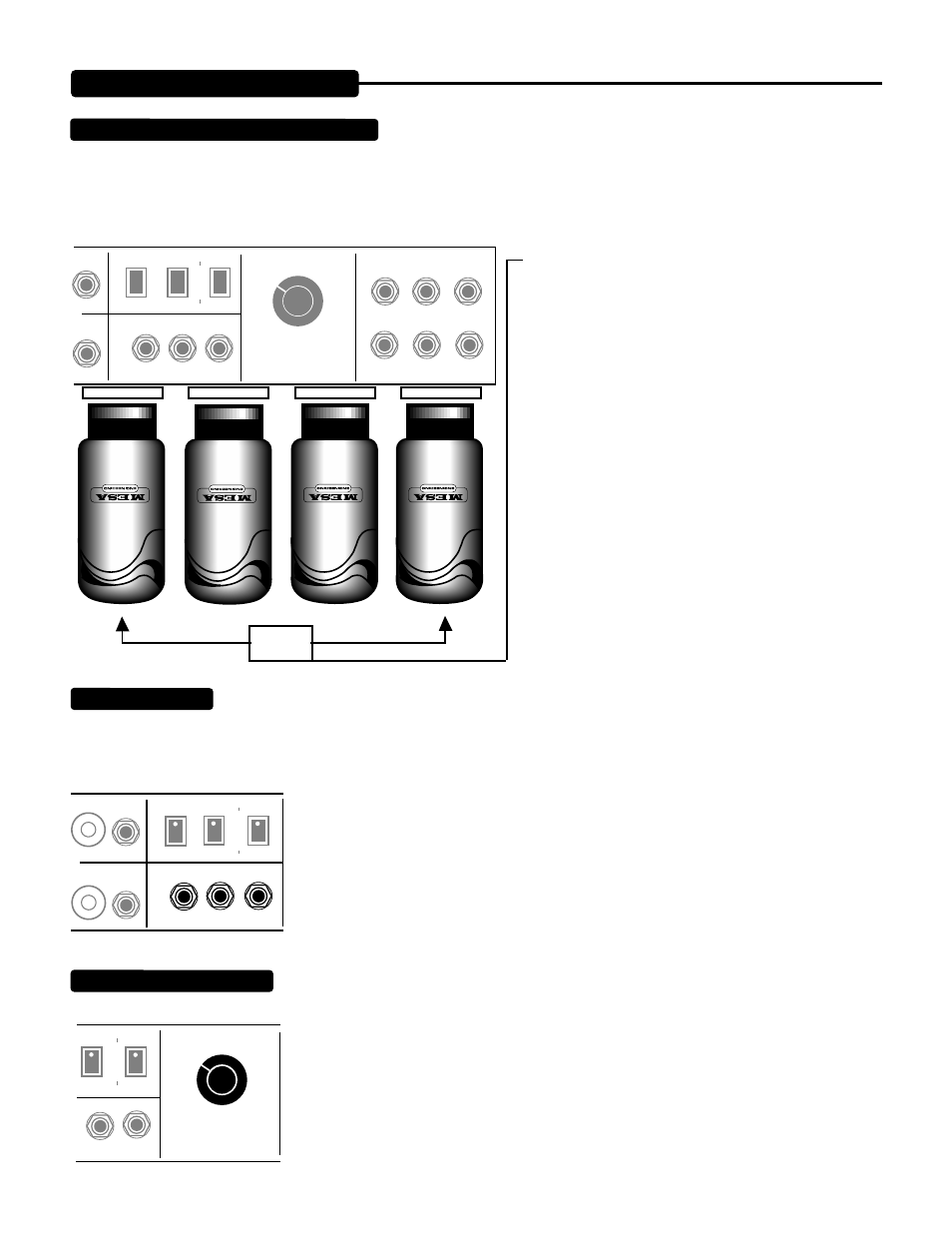
These two outer tubes can be substituted with EL-34’s.
CAUTION: Place amp in STANDBY mode when changing
tubes.
CAUTION: Tubes can become very HOT...they can cause
injury. Use care in removing tubes that are warm/hot and
never remove a tube by pulling on the glass. Instead, grab
the tubes socket or base and rock the tube from side to
side while pulling gently downward.
Speaker jacks for both 8 ohm and 4 ohm loads are provided. CAUTION: A speaker (or load resistor) must remain connected to
a speaker output on your MARK IV to prevent damage to the power tubes and transformer! (For silent recording, merely pull
the designated switch on the OUTPUT LEVEL control located on the Front Panel and do not disconnect the speaker.)
Two 4 ohm jacks are provided and should be used when you wish to run two 8 ohm speakers
or cabinets. (This is because two 8 ohm loads connected in parallel present a combined load
to the amplifier of 4 ohms.) Speaker mis-matching is not a cause for great concern - unless the
combined load is considerably less than the rated impedance. If, for example, you run two 4
ohm cabinets - each plugged into a 4 ohm jack - the amplifier would “see” 2 ohms as the total
load. And while this will not cause immediate damage, it will result in shortened power tube
life. Mis-matching on the high side is always preferable, if you have no choice.
This switch determines the method of control over your MARK IV’S switching functions. The first position activates the footswitch.
The next three positions select the individual modes manually.
The last position enables the use of the EXTERNAL SWITCHING jacks. If ever the switching
functions seem to operate incorrectly, always check that the MODE SELECTOR switch is set
to the proper position.
REAR VIEW
MKIV
(Continued)
POWER TUBE SUBSTITUTION: (Continued)
POWER AMP
TRIODE
SIMUL-CLASS
HARMONICS
PENTODE
CLASS A
SPEAKERS
8 OHM
4 OHM
4 OHM
MID GAIN
LEAD VOICING
EXTERNAL SWITCHING JACKS
RHYTHM 1
RHYTHM 2
LEAD
CLASS A/ SIMUL FX LOOP
EQ
MODE SELECT
LEAD
EX SW
FT SW
RHY 1
RHY 2
HANDBUILT IN PETALUMA CALIFORNIA
OUT
44 NG WHT
6L6 GC
STR 454
44 NG WHT
6L6 GC
STR 454
44 NG WHT
6L6 GC
STR 454
44 NG WHT
6L6 GC
STR 454
NOTE:
SPEAKER JACKS:
LEVEL
OUT
POWER AMP
TRIODE
SIMUL-CLASS
HARMONICS
PENTODE
CLASS A
SPEAKERS
8 OHM
4 OHM
4 OHM
MID GAIN
LEAD VOICING
2
3
4
5
6
7
8
9
1
0
1 0
2
3
4
5
6
7
8
9
1
0
1 0
MODE SELECTOR SWITCH:
SIMUL-CLASS
HARMONICS
CLASS A
4 OHM
4 OHM
MID GAIN
LEAD VOICING
MODE SELECT
LEAD
EX SW
FT SW
RHY 1
RHY 2
HANDBUILT IN PETALUMA CALIFORNIA