MTD 31AE5MLG729 User Manual
Page 16
12
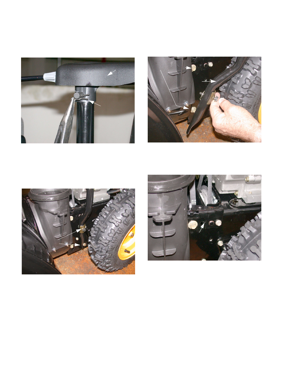
14.5. Use needle nose pliers to remove the hairpin clip
from the clevis pin securing the 4-way chute
control assembly to the chute support tube.
Remove the clevis pin. See Figure 36.
14.6. Remove the control assembly and set it on the
engine.
14.7. Using a ½” socket, remove the AB screw secur-
ing the lower portion of the chute support tube to
the frame. See Figure 37.
14.8. Using a ½” socket, remove the TT screw, handle
tab and washer securing the support tube to the
frame. Remove the support tube from the unit.
See Figure 38.
14.9. Using a 3/8” socket, remove the AB screw
securing the auger cable guide bracket to the
frame. See Figure 39.
14.10.Using a ½” socket, remove the 4 bolts (2 on
each side) securing the auger housing assembly
to the wheel drive frame.
Figure 36
4-Way Chute Control
Hairpin Clip
Figure 37
AB screws
Figure 38
Support Tube
Frame Screws
Figure 39
Auger Cable Bracket
- E6A4E (28 pages)
- H Style 600 Series (24 pages)
- E644F (28 pages)
- 317E140-000 (12 pages)
- 3BA (20 pages)
- 3BA (20 pages)
- 31A-020-900 (50 pages)
- 310-400 (4 pages)
- 737-0168 (28 pages)
- 313-205 (8 pages)
- 769-01275C (28 pages)
- OEM-190-032 (19 pages)
- E150 (19 pages)
- E663G (28 pages)
- 770-10278 993 (24 pages)
- Style L (48 pages)
- 6DE (28 pages)
- 310-180-000 (16 pages)
- 285 (28 pages)
- 312-980I000 (28 pages)
- C Style (28 pages)
- C Style (28 pages)
- 769-01276A (28 pages)
- E173 (24 pages)
- 31AS2B5 (13 pages)
- 261 (18 pages)
- 769-04179 (56 pages)
- 6FE (28 pages)
- E664F (32 pages)
- 614E (32 pages)
- 662E (32 pages)
- 550 (36 pages)
- 31AH5C3F401 (28 pages)
- S265 (16 pages)
- 315-960-000 (32 pages)
- 2P5 (24 pages)
- 31AE993I401 (28 pages)
- 190-768 (8 pages)
- 179cc (24 pages)
- 663 (28 pages)
- 330 Series (16 pages)
- 769-04095 (56 pages)
- 2B5 & 295 (32 pages)
- E760 (28 pages)
- 150 (32 pages)