External dtv receiver with component video, Hdmi device, Important – MITSUBISHI ELECTRIC WS-65517 User Manual
Page 21: Figure 11. connecting an hdmi device, Ch 3 ch 4, Risk of electrical shock do not open, Ant-1 main – (dtv/cable /vhf/uhf)
21
Connecting an HDMI Device or
External DTV Receiver with Component Video
See Appendix B for component video signal
compatibility information.
For digital audio connections, see your DTV
Receiver and A/V Receiver Owner’s Guides.
IMPORTANT
DTV Receiver (with YPrPb connections)
VIDEO
Y
Pr
Pb
S-VIDEO
VCR
CONTROL
PHONE JACK
RF
REMOTE
OUT TO TV
CH 3
CH 4
CAUTION
RISK OF ELECTRICAL SHOCK
DO NOT OPEN
DIGITAL
AUDIO OUT
White
Red
Incoming
Antenna
or Cable
SATELLITE IN
IN FROM ANT
or
to antenna,
cable or satellite
AUDIO
L
R
AUDIO
L
R
VIDEO
S-VIDEO
VIDEO
AUDIO-
LEFT/
S-VIDEO
VIDEO
AUDIO-
LEFT/
T
T
ANT-1
MAIN
–
(DTV/CABLE /VHF/UHF) –
Y
Pb
Pr
AUDIO-
LEFT/
(MONO)
AUDIO-
RIGHT
COMPONENT
YPbPr (480i/480p/1080i)
2
1
White
Red
1.
1.
2.
2.
3.
3.
4.
4.
Figure 12. Connecting an External DTV Receiver with
Component Video Connections
External DTV Receiver with
Component Video
Figure 12
A coaxial splitter, RCA video cables and audio cables are
required. These are not included with the TV.
1. Connect the outside antenna, cable or satellite to
ANT or SATELLITE IN on the DTV receiver (see your
DTV receiver’s owner’s guide for instructions and
cable compatibility).
2. Connect the incoming terrestrial antenna or cable
(not satellite) to ANT-1 on the TV back panel
(a coaxial splitter, available at most electronic
supply stores, may be required to complete this
installation).
3. Connect RCA-type cables from the YPrPb outputs
on the DTV receiver to either Component 1 or
2 on the TV back panel, matching the correct
connections:
DTV Receiver to TV Back panel
•
Y to Y
• Pr to Pr
•
Pb to Pb
4. Connect the L (left) and R (right) audio cables from
the DTV receiver to Component 1 or 2 AUDIO LEFT
and AUDIO RIGHT on the TV back panel. If you
connected the YPrPb outputs to Component 1, also
use Component 1 to connect the audio cable. The
red cable connects to the R (right) channel and the
white cable connects to the L (left) channel.
Note: To utilize the benefits of a digital A/V
receiver, connect your DTV receiver’s digital
audio out to a digital input on your digital A/V
receiver.
NG
PRODUCT
A N I C A L
CH AR E
SAFE TY.
E P L A C E
D I C AT E D
LY WITH
S G I V E N
SERVICE
LT
LL A
TT GE AT
A
A
RE ME NT
S E RV ICE
RE. HIGH
GEROUS
CING TO
O N N E L .
E SAME
SAFETY.
Y
Y
SECOND
VOLT
L
L A
T
T GE
DE LEAD
GE HIGH
NOT TO
AUDIO-
LEFT/
T
T
TPUT
UDIO 2
TV back panel
Digital Video
Digital Audio
HD-6000 Receiver
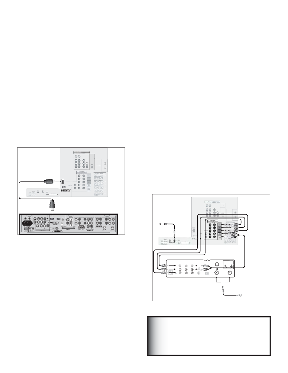
Figure 11. Connecting an HDMI Device
HDMI Device
Figure 11
An HDMI-to-HDMI cable is required. This is not included with
the TV. It may be available at your local electronics retailer.
Connect an HDMI cable from the TV back panel to the
HDMI device output. HDMI devices provide video and
audio through this cable, so no other connection is
required.
Note: This connection supports PCM linear stereo
audio only. For Dolby Digital or other digital
surround sound, you will need to connect the
optical or coaxial digital audio output of the
HDMI device directly to your AV receiver.