3. trigger hold switch – Miller Electric S-74D User Manual
Page 22
OM-1500-10 Page 18
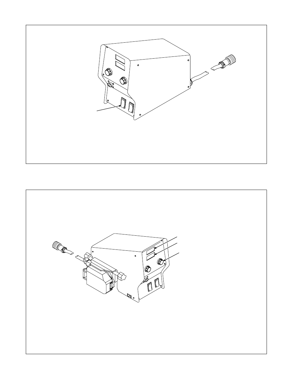
6-3. Trigger Hold Switch
1
Trigger Hold Switch
Trigger hold allows the operator to weld with-
out holding the gun trigger.
•
To use the trigger hold function, place the
trigger hold switch in the On position.
•
The operator must hold the trigger for a mini-
mum of 2 seconds, but not longer than 6
seconds before releasing it. Welding will
continue when the trigger is released.
•
To stop welding, press the trigger again.
1
802 828-A
6-4. Voltage Control And Digital Meters (For Models With Meters Only)
3
802 827-A
1
2
1
Voltmeter
The voltmeter displays actual or
preset voltage from the welding
power source through the 14−pin
control cable.
2
Wire Speed Meter
The wire speed meter is factory set
to display inches per minute. If dis-
play of meters per minute is de-
sired, see Section 5-8.
3
Voltage Control
Use control to adjust voltage output
of welding power source.
.
You can adjust the preset volt-
age display on the wire feeder
to match your power source’s
display by adjusting P2 on mo-
tor control board PC1. See
Section 7-2 for location of P2.