2. equipment connection diagrams – Miller Electric D-75S User Manual
Page 17
OM-228 322 Page 13
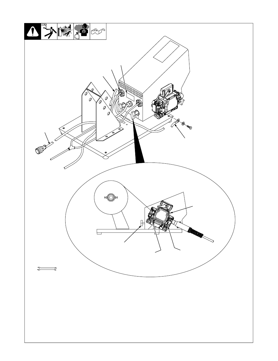
5-3. Rear Panel Connections And Rotating Drive Assembly
804 557-B / 804 184-B
2
1
14-Pin Control Cable - 10 Ft (3.0 m)
2
Shielding Gas Valve Fittings
Requires fitting with 5/8-18 right-hand
threads. Connect customer-supplied gas
hose.
3
Jumper Weld Cable
.
If welding at 350 amps or less, connect
jumper weld cable to connection point
B. Route cable around back of feeder.
(See illustration).
.
If welding at 350 amps or more, con-
nect jumper weld cable to connection
point A. Route cable around front of
feeder.
Left side of drive assembly has a screw to
secure jumper weld cable at connection
point B. To move jumper weld cable to con-
nection point A remove screw from point B
to use in point A.
Right side of drive assembly has screws to
secure jumper weld cable and weld cable to
connection points A and B.
4
Weld Cable
Connect weld cable to connection point A
on right side of drive assembly.
5
Drive Assembly
6
Drive Assembly Rotation Knob
To rotate the drive assembly, loosen drive
assembly rotation knob, rotate drive as-
sembly, and tighten knob.
7
Rating Label Location
9/16, 5/8 in
Tools Needed:
1
7
3
5
6
Connection
Point A
Connection
Point B
Left Side Shown
4