3. volt-ampere curves, 4. installing gas supply – Miller Electric INTEGRA 201/241 User Manual
Page 10
OM-188 414 Page 6
2-3.
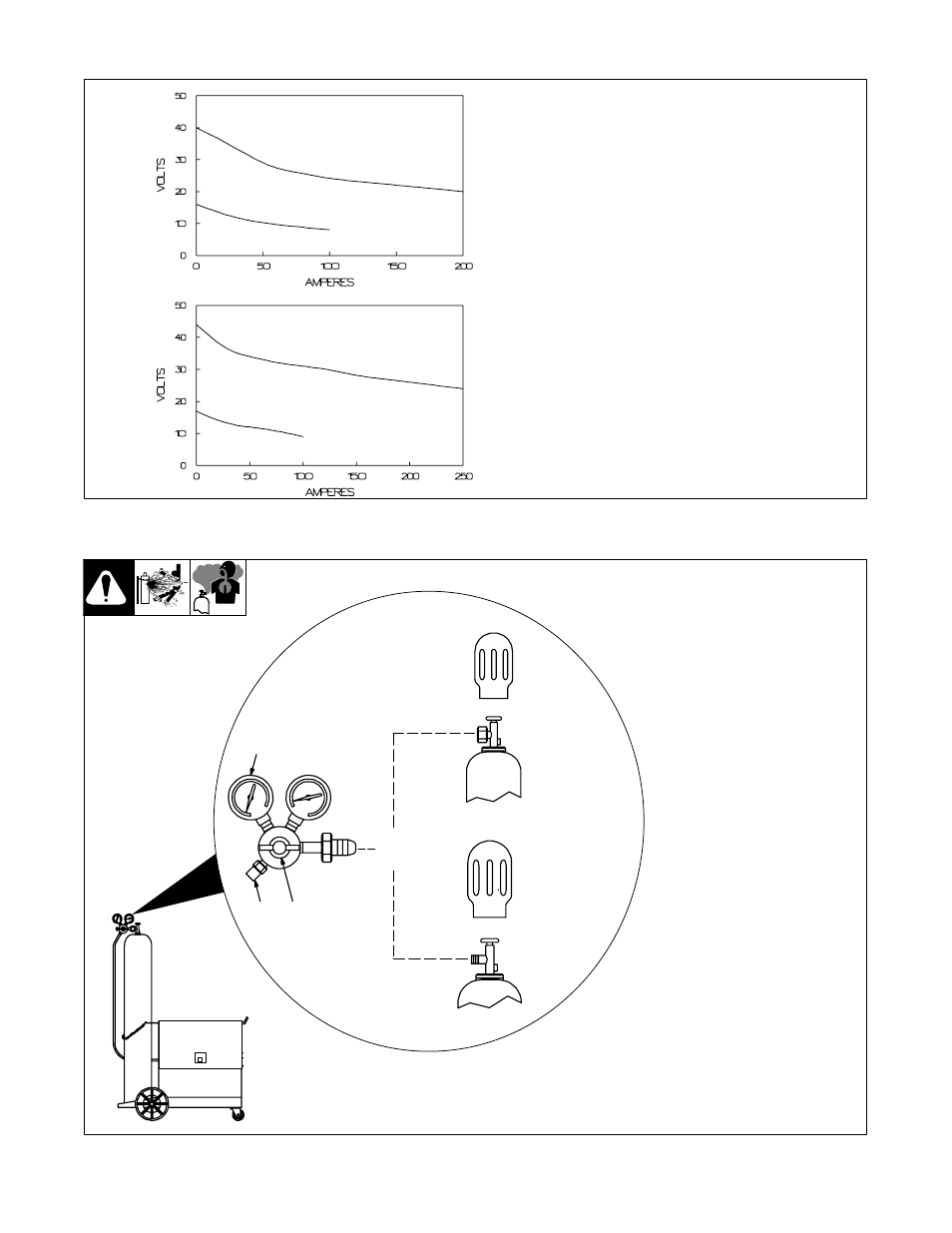
Volt-Ampere Curves
1
Normal Volt-Ampere Curves
The volt-ampere curves show the
normal minimum and maximum
voltage and amperage output capa-
bilities of the welding power source.
Curves of other settings fall be-
tween the curves shown.
Model 201
Model 241
dwg. 802004, 802003
2-4.
Installing Gas Supply
Ref. ST-148 265-B / Ref. ST-149 827-B / Ref. ST-158 697-A
2
CO
2
Gas
1
Argon Gas
OR
3
Chain gas cylinder to running gear,
wall, or other stationary support so
cylinder cannot fall and break off
valve.
1
Regulator/Flow Gauge
Install so face is vertical.
2
Gas Hose Connection
3
Flow Adjust
Typical flow rate is 20 cfh (cubic
feet per hour). Check wire man-
ufacturer’s recommended flow
rate. This flow gauge can be
adjusted between 5 and 25 cfh.
See also other documents in the category Miller Electric Tools:
- OM-2241 (32 pages)
- ICE-27C (36 pages)
- Arc Welding Power Source (4 pages)
- INVISION 456 CC (44 pages)
- Welder (132 pages)
- SS-75D12 (44 pages)
- Load Bank LBP-350 (2 pages)
- OM-193 084E (36 pages)
- 750MPa (2 pages)
- APT-1000 (20 pages)
- OM-220 390F (48 pages)
- 271 (48 pages)
- Welding (32 pages)
- DC (72 pages)
- OM-129 (70 pages)
- XLi (24 pages)
- S-64 (36 pages)
- ICE-27T (36 pages)
- PipePro 304 (76 pages)
- AA40GBU (28 pages)
- D-64 (40 pages)
- Auto Arc XLT 165 (48 pages)
- 185 DX (56 pages)
- S-32S (4 pages)
- Big 40 DC/TIG 55500 A (8 pages)
- Big Blue 600D (60 pages)
- Millermatic 140 (60 pages)
- pmn (36 pages)
- LMSW Series (2 pages)
- 1250 (46 pages)
- Trailblazer Pro 350 D (8 pages)
- TS (76 pages)
- S-22P12 (28 pages)
- 602 (40 pages)
- Axcess 300 (56 pages)
- MOG-400 (40 pages)
- WC-24 (20 pages)
- Big Blue 502P (64 pages)
- Dimension 1000 (44 pages)
- DS-74DX12 (52 pages)
- 350 VS (36 pages)
- 24A (32 pages)
- GA-16C (12 pages)
- Big Blue 502D (116 pages)
- OM-229 038D (36 pages)