Monte Carlo Fan Company 8ATR44 User Manual
Page 3
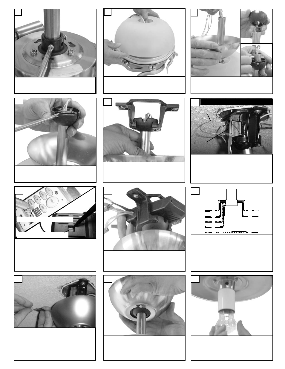
Carefully lift fan assembly onto mounting brack-
et. Rotate fan so that the notch on the ball
engages the ridge in the mounting bracket. This
will allow hands-free wiring.
11
7
Make wire connections to power source using
wire nuts provided. Make sure that no filiments
are outside of the wirenut. After making the
wire connections, the wires should be spread
apart with the grounded conductor and the
equipment-grounding conductor on one side of
the outlet box and ungrounded conductor on
the other side of the outlet box.
16
For Canadian installation and for USA fan and
light kit combinations over 35 lbs, in both flush
and downrod mode the safety cable must be
installed into the house structure beams using
the 3” lag screws provided. Make sure that
when the safety cable is fully extended the
leadwires are longer than the cable and no
stress is placed on the leadwires.
12
Safety cable installation
Safety Cable
Lag Screw
Raise the canopy up and align the
two holes in the canopy with the two
holes in the hanger bracket. Secure
with two screws provided.
17
Tighten both yoke set screws and
lock nuts to further secure downrod.
8
Install upper glass over downrod
onto fan body.
9
Install canopy over downrod.
Caution: Replace pin and ball onto
downrod.
10
Tighen set screw loosened in step 5.
Set dip switches on the Remote Transmitter and Remote
Receiver to the same settings. This must be done so the
units will communcate properly. If you have other fans you
can set to control from one transmitter by setting both
receivers the same as the transmitter. If you have more
than one fan with remote. You can set the dip switches to
different positiosns to have seperate control.
Remote Transmitter Dip swtiches
Remote Receiver Dip switches
13
Install remote receiver by sliding into opening
in the mounting bracket. Make sure that the dip
switches on the transmitter and the receiver are
set to the same positions.
14
white
Black
Make wiring connections as indicated above.
White from fan to white from remote marked
N. Orange from fan to Orange from remote
marked Light/up. Blue from fan to blue from
remote marked down light. Black from fan to
Black from remote marked L. White from
house to white from remote marked AC N .
Black from house to Black from remote
marked AC L. Connect all green ground wires
to Ground wire from House.
orange
blue
Green
white
black
House
Fan
15
Install 1 x 100 watt Edison base
bulb.
18