Fs2/fs2sp concrete saw — maintenance, W — transmission assy – Multiquip Whiteman Concrete Saw FS2 User Manual
Page 32
PAGE 32 — MQ-WHITEMAN FS2/FS2SP CONCRETE SAW — PARTS & OPERATION MANUAL — REV. #2 (06/26/06)
FS2/FS2SP CONCRETE SAW — MAINTENANCE
Blade Shaft Bearing Replacement
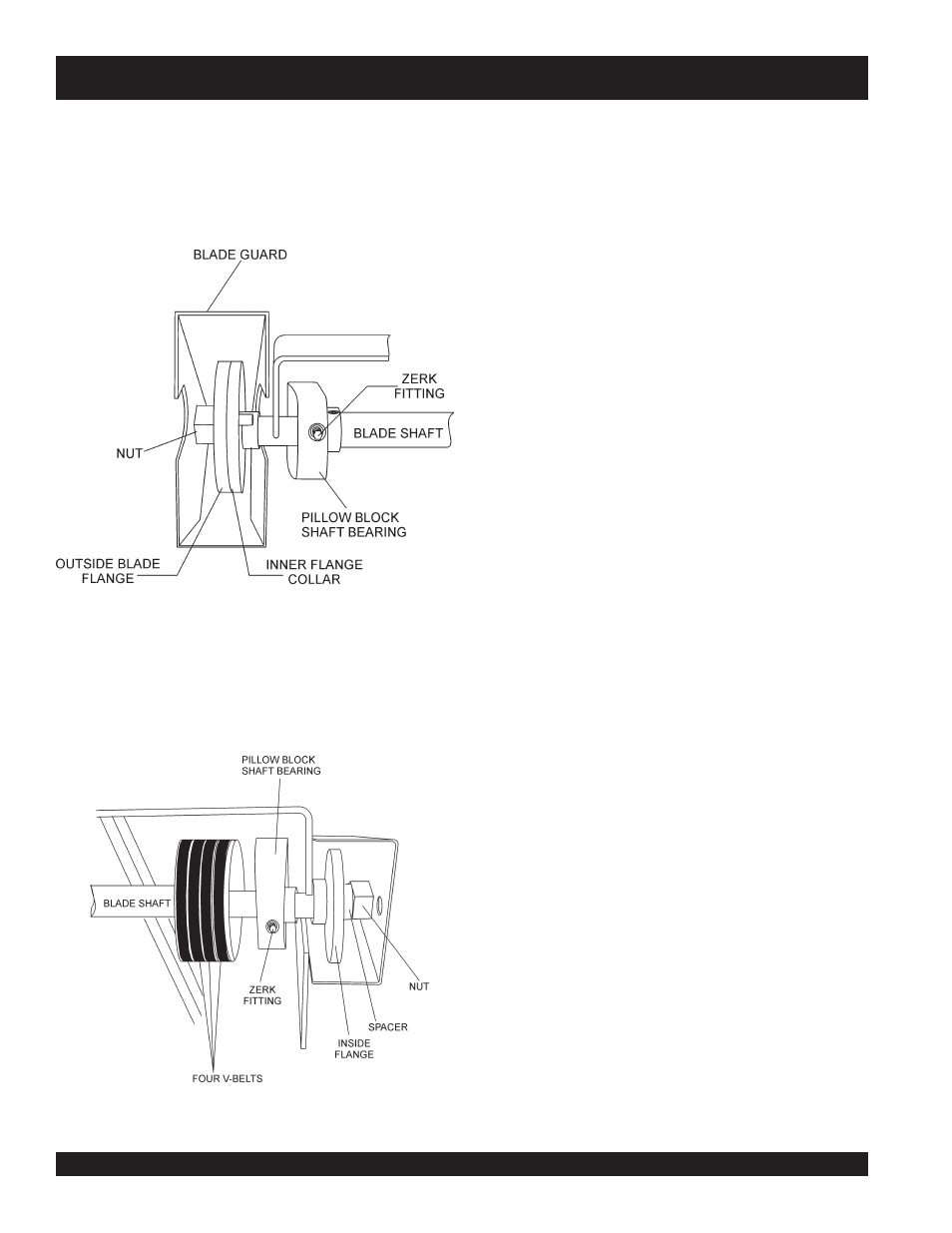
The FS2/FS2SP is supported by “tapped base lock collar (w/set
screw)’ self-aligning blade shaft bearings. These heavy duty
bearings support the 1-1/4 blade shaft, and have grease (zerk)
points (Figures 29 and 30) conveniently located for service.
Figure 29. Right-Side Shaft Bearing
1. Reference pages 44 (
Blade Shaft Assembly
) and
46 (
Engine Mount Assembly
).
2. Its recommended to replace both left & right hand bearings
collectively.
Figure 30. Left-Side Shaft Bearing
3. To loosen the tension on the four V-Belts perform the follow-
ing:
z Remove the Belt Guard, item, page 48, item 6 (Pointers
and Covers Assembly)
z Loosen the Carriage Bolt, page 46, item 7 (Engine
Mount Assembly).
z Loosen the Hex Head Cap Screws, page 46, item 4
(Engine Mount Assembly).
z Rotate the engine down to provide slack in the V-Belts
Replacement of the Blade Shaft Bearings
4. Perform the following to replace the blade shaft bearings:
z Remove
blade flanges
(page 44, items 7 and 8,
Blade
Shaft Assembly
) as required to permit the Shaft Bearing(s)
to slide off the blade shaft.
z Loosen/remove
shaft bearing(s)
hex head cap screws
,
page 44, item 11.
z Loosen
set screw
on the blade shaft bearing collar.
z Slide “old” bearing(s) off the blade shaft and replace with
“new” bearing(s)- grease (zerk) fitting pointing forward, and
the lock collar oriented to the “right" as you face the saw.
5. Loosely bolt the bearing(s) into place on the saw frame, then
ensure the alignment by referencing past bearing position-
ing.
6. Tighten the
hex head cap screws
, page 44, item 11 to
secure the shaft bearing (s) to the frame.
7. To complete the re-installation process, reverse the order of
the above mentioned steps. For V-belt adjustment and
tensioning see pages 31 (Figures 27 and 28) and 33 (Figure
32).
W — TRANSMISSION ASSY.