Monte Carlo Fan Company 5DOR52 User Manual
Page 4
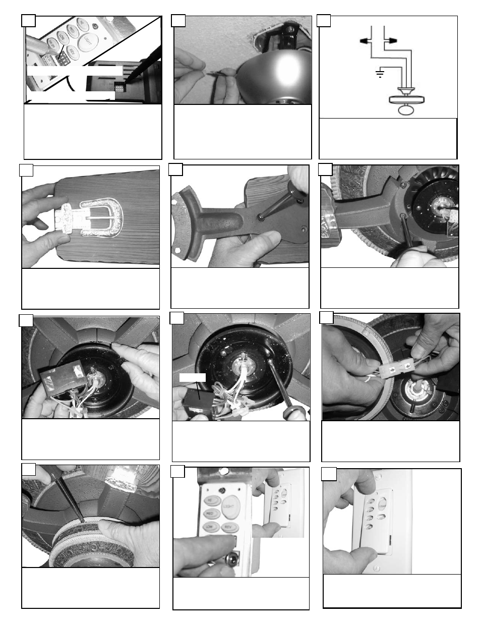
Place blade arms onto the other side of the
blade and aligning holes. Insert screws with
fabric washers through the holes and tighten
securely.
23
Check the motor for plastic shipping stabilizer
tabs, and remove them if they are present.
Attach blade assembly to motor by tighten
screws securely.
24
After attaching blades; install the switch hous-
ing with the three screws previously removed.
28
Tighten the three screws securely holding the
plate for the switch housing. Remove the dou-
ble sided tape from capacitor and stick capaci-
tor to plate.
26
Loosen the 2 screws with key slots and remove
the screw without key slot. Pass plug and
capacitor through hole in plate. Take plate and
place over the 2 screws with key slots and
twist to hold in place.
25
Place floating brackets onto blades aligning
holes in blade with the floating bracket.
22
Make sure to connect the plug from remote to
the plug coming from fan body according to the
arrows indicated on the plugs, otherwise the
remote will be damaged.
27
Capacitor
Remove cover by snaping off from
top or bottom. Install 12V battery
into wall remote. Duracell MN21 /
Eveready A23 / GP 23A all 12V.
29
Attach cover of remote by placing
over buttons and snaping into place.
30
Make wire connections to power source using
wire nuts provided. Make sure that no filiments
are outside of the wirenut. After making the
wire connections, the wires should be spread
apart with the grounded conductor and the
equipment-grounding conductor on one side of
the outlet box and ungrounded conductor on
the other side of the outlet box.
20
Set dip switches on the Remote Transmitter and Remote
Receiver to the same settings. This must be done so the
units will communcate properly. If you have other fans you
can set to control from one transmitter by setting both
receivers the same as the transmitter. If you have more
than one fan with remote. You can set the dip switches to
different positiosns to have seperate control.
Remote Transmitter Dip swtiches
Remote Receiver Dip switches
19
Make wiring connections as shown black wire
from house to black wire from fan. White wire
from house to white wire from fan. Connect all
green ground wires to ground wire from house.
Refer to diagram above.
black
black
white
green ground
white
21
green ground
AC 120 V
input