Know your snow thrower, Warning – MTD 3AA & 3CA User Manual
Page 8
8
Become familiar with all
the controls on the snow
thrower and their proper
operation. Know how to
stop the machine and
disengage them quickly.
Never make adjustments to
the chute assembly unless
both auger and drive
controls are disengaged
and the operator is stand-
ing beside the unit.
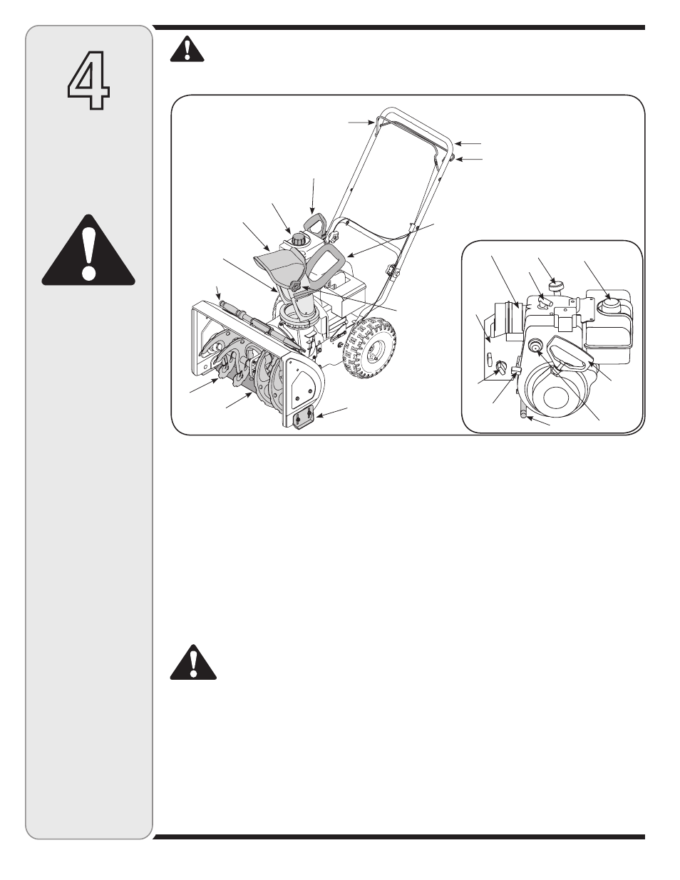
4
Know
Your Snow
Thrower
Throttle Control
The throttle control is located on the engine. It regulates
the speed of the engine and also stops the engine.
Drive Control
Located on the underside of the upper handle, the drive
control is used to engage/disengage wheels. Squeeze
the drive control against the upper handle to engage the
wheels; release to disengage.
Auger Control
The auger control is adjacent to the upper handle.
Squeeze the auger control against the upper handle to
engage the augers; release to disengage the augers.
WARNING: Never make adjustments to
the chute assembly unless both auger
and drive controls are disengaged and
the operator is standing beside the unit.
IMPORTANT: Refer to the Auger Control Test in the
Operation section prior to operating your snow thrower.
Read and follow all instructions carefully and perform
all adjustments to verify your snow thrower is operating
safely and properly.
Gasoline Cap
Remove gas cap to add fuel. Unit runs on regular gas.
Chute Handle
The direction of snow throwing corresponds to the
direction of the chute opening. Use the chute handle to
turn the chute assembly in the direction you wish to throw
the snow.
Chute Knob
The distance snow is thrown can be adjusted by either
raising or lowering the upper chute. Loosen the chute
knob on the side of the upper chute to adjust. Pivot the
upper chute to desired position, and retighten the chute
knob.
Ignition Key
The ignition key is necessary for the engine to start.
Insert key and snap in place; Do not turn it to start/stop
the unit. Remove key when the unit is not in use.
Shave Plate
The shave plate maintains contact with pavement as
the snow thrower is propelled, allowing snow close to
pavement’s surface to be discharged.
Skid Shoe
The space between the shave plate and the ground can
be adjusted. For close snow removal, place skid shoes in
the low position. Use middle or high position when area to
be cleared is uneven or on gravel surfaces.
Figure 7
Compare Figure 7 with your equipment and follow description of controls, given below, to become familiar with their
operation.
WARNING: Be familiar with all the controls on the snow thrower and their proper operation. Know
how to stop the machine and disengage them quickly.
WARNING
Muffler
Spark
Plug
Oil Fill
Fuel Cap
Starter
Handle
Primer
Oil Drain
Throttle
Control
Choke
Carburetor
Cover
Auger Control
Skid Shoe
Shave Plate
Auger
Clean-Out Tool
Chute Assembly
Upper Chute
Gasoline Cap
Starter Rope
Upper Handle
Drive Control
Chute Handle
Chute Knob