McIntosh MC1201 User Manual
Page 13
13
Technical Description
Design Philosophy
The design philosophy incorporated in the MC1201 in-
volved several different techniques, all based on sound sci-
entific logic. Every stage of voltage or current amplifica-
tion must be as linear as possible prior to the use of nega-
tive feedback. McIntosh engineers know how to properly
design negative feedback circuits so they contribute to the
extremely low distortion performance expected from a
McIntosh amplifier. The typical McIntosh owner would
never accept the approximately 100 times higher distortion
of many non-feedback designs.
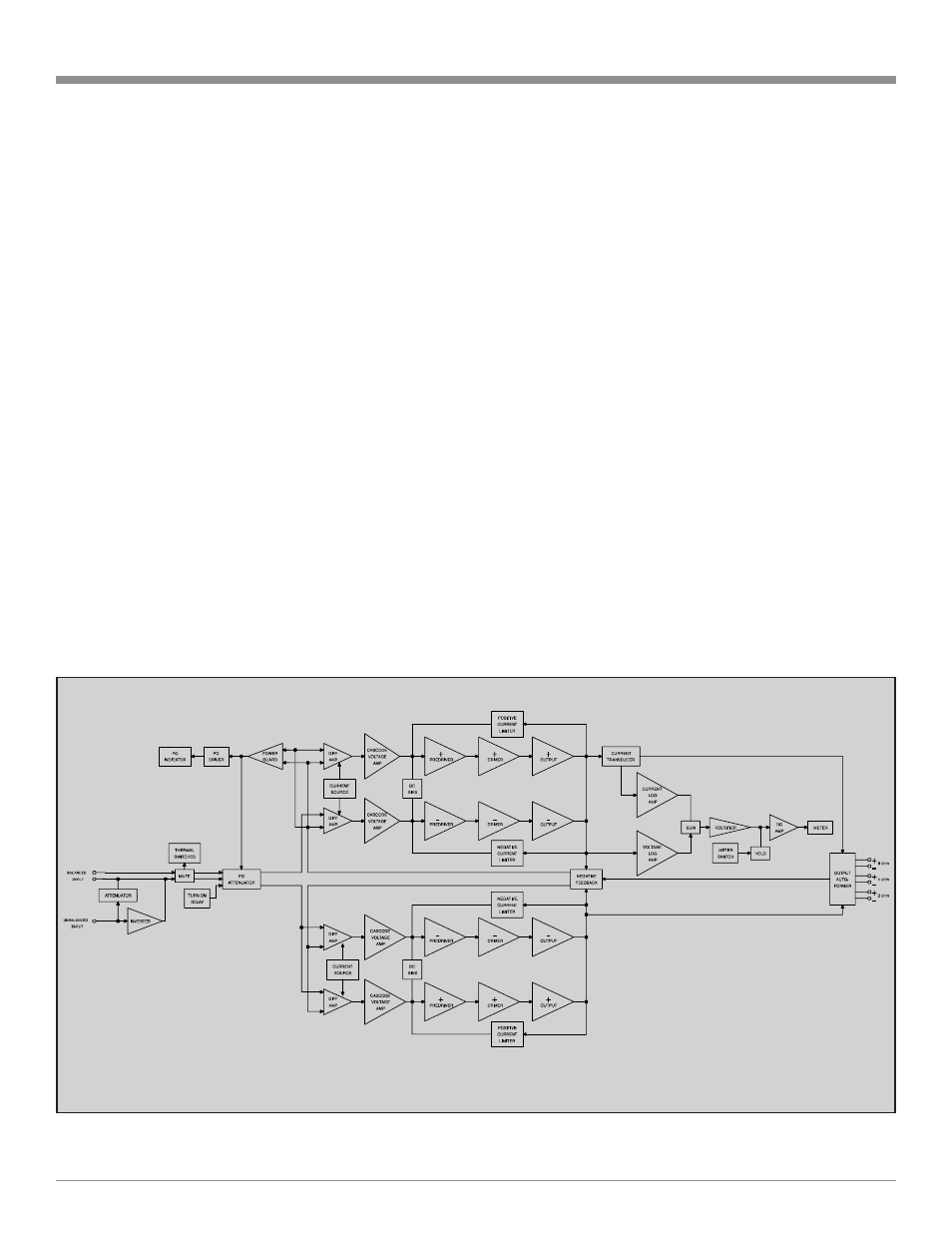
Double Balanced Push-Pull design is used from input to
output. Each half of the amplifier contains complimentary
balanced circuitry. The resulting double balanced configu-
ration cancels even order distortion. Refer to figure 12.
All transistors are selected to have nearly constant cur-
rent gain over the entire current range they must cover.
Output transistors in particular, have matched uniform cur-
rent gain, high current bandwidth product and large active
region safe operating area. An automatic tracking bias sys-
tem completely eliminates any trace of crossover distor-
tion. Precision metal film resistors and low dielectric ab-
sorption film capacitors are used in all critical circuit loca-
tions.
Figure 12
The output signals of the two balanced circuits are
coupled together in the unique McIntosh MC1201 Output
Autoformer. It provides low distortion power transfer at
frequencies from below 20Hz to well beyond 20,000Hz
with optimum impedance points of two ohms, four ohms
and eight ohms. The unequaled expertise of McIntosh in
the design and manufacturing of autoformers is legendary
in the high fidelity industry.
The high efficiency circuit design of the MC1201 con-
tributes to low operating temperatures. More than 290
square inches of heat sink area keep the MC1201 operating
safely with convection cooling. No fans are needed.
Autoformers
All solid state power amplifier output circuits work best
into what is called an optimum load. This optimum load
may vary considerably from what a loudspeaker requires.
In the case of more than one loudspeaker connected in par-
allel, the load to the power amplifier may drop to two ohms
or even less. A power amplifier connected to a load that is
lower than optimum, causes more output current to flow,
which results in extra heat being generated in the power
output stage. This increase in temperature will result in a
reduced life expectancy for the amplifier.
Block Diagram
of the
Amplifier and Meter Circuitry