Operational setup, Connectors – Marshall electronic V-R171P-HDAV-R171P-HDA User Manual
Page 3
3
4
Operational Setup
1. Unpack the V-R171P-HDA and accompanying power supply. Physically inspect for any damage that may have occurred
during shipping. Should there be any damage, immediately contact Marshall Electronics at 800-800-6608. If you are not
located within the continental united states call +1 310-333-0606.
2. Install in your desired location.
3. Connect required cables for signal input and output.
4. Attach battery (Optional) or power connection from power supply to the back of the unit.
5. Plug the power supply into the A.C. source
6. Turn on the V-R171P-HDA by depressing the power switch located on the front of the unit.
Refer to Page 4 picture for location of switch settings.
7. Perform input selections and screen adjustments as detailed in following sections of this document.
Marshall Electronics
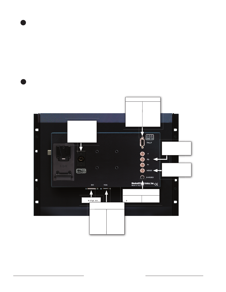
12 VDC from
power supply
4 Pin Male XLR
Pin 4 - Pos
Pin 1- Neg
DVI-D In
Component Video
75Ω Terminated
Composite
Video
75Ω Terminated
Pin1 - GND
Pin2 - GND
Pin3 – Y in
Pin4 – C in
S-Video IN
4 Pin Din (Female)
Pin1-Red IN
Pin2-Grn IN
Pin3-Blu IN
Pin4-
Pin5-
Pin6-Gnd
Pin7-Gnd
Pin8-Gnd
Pin 9-
Pin10-
Pin11-
Pin12-
Pin13-
Pin14-HSync
Pin15-VSync
SXGA IN
HD-15 Female
Pin1- Green
Pin2- Red
Pin3-Amber
Pin4 Ground
Pin5- Ground
Pin6-
Pin7-
in8-
Pin 9-
Pin10-
Pin11-
Pin12-
Pin13-
Pin14-
Pin15-
Tally IN HD-15 Female
5
Connectors