1 introduction, Introduction – Multi-Tech Systems BL-Series User Manual
Page 108
108
MultiModemBL User Guide
9.1
Introduction
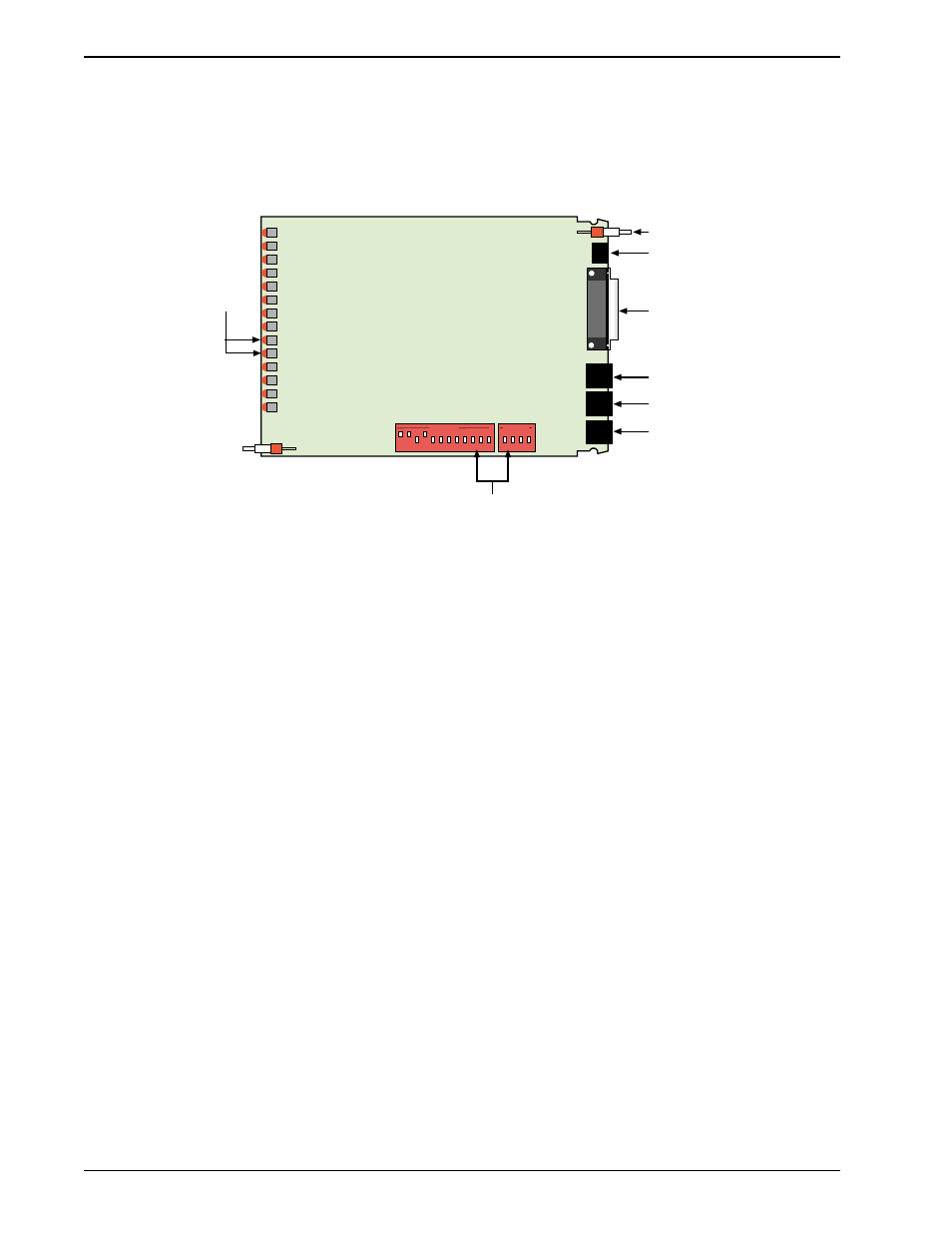
There are several DIP-Switch options on the modem’s printed circuit (PC) board. The DIP-Switches
are accessible through a cut-out on the side of the modem. This chapter explains the modem’s
printed-circuit board options. Sixteen DIP-Switch settings and the modem's speaker volume control
are explained in detail, including all default settings.
Phone Jack
Dial-up Jack
Lease-Line
Jack
RS-232/V.24
Connector
Power Jack
Power Switch
LED
Indicators
OPEN
13 14 15 16
OPEN
1 2 3 4 5 6 7 8 9 10 11 12
16-position DIP-switches
Figure 9-1. PC Board (BL models)
Note: There is no Phone connector on BLK models