Monte Carlo Fan Company 5MAR52 User Manual
Page 3
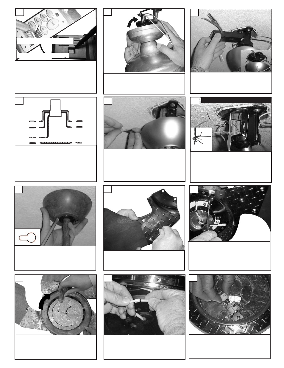
Carefully lift fan assembly onto mounting
bracket. Rotate fan so that the notch on the
ball engages the ridge in the mounting bracket.
This will allow hands-free wiring.
Install 3 allen screws, washers, and nuts per
blade and tighten securely with allen wrench.
Repeat for all 5 blades. Curve of blade goes
down which is labeled on blades.
14
Check the motor for plastic shipping stabilizer
tabs, and remove them if they are present.
Attach blade assembly to motor using the motor
screws and washers provided. Tighten screws
securely. Next attach light kit or blanking plate
to the fan.
15
Make wire connections to power source using
wire nuts provided. Make sure that no filiments
are outside of the wirenut. After making the
wire connections, the wires should be spread
apart with the grounded conductor and the
equipment-grounding conductor on one side of
the outlet box and ungrounded conductor on
the other side of the outlet box.
11
white
Red
Make wiring connections as indicated above.
White from fan to white from remote marked
N. Blue from fan to blue from remote
marked down light. Black from fan to Red
from remote marked L. White from house to
white from remote marked AC N . Black from
house to Black from remote marked AC L.
Connect all green ground wires to Ground
wire from House.
blue
Green
white
black
House
Fan
10
Install remote receiver by sliding into opening in
the Mounting bracket. Make sure that the dip
switches on the Transmitter and the Receiver
are set to the same position. See Fig 25 for
remote operation
9
8
Plug white wire from fan to white wire from
light kit. Then plug black from fan to black from
light kit.
17
Loosen the 2 screws with key slots and remove
the screw without key slot. Take plate and
place over the 2 screws with key slots and
twist to hold in place. Tighten the 3 screws
securely holding the plate for the switch hous-
ing.
16
Raise the canopy up and align the two holes in
the canopy with the two holes in the hanger
bracket. Secure with two screws provided.
13
Set dip switches on the Remote Transmitter and Remote
Receiver to the same settings. This must be done so the
units will communcate properly. If you have other fans you
can set to control from one transmitter by setting both
receivers the same as the transmitter. If you have more
than one fan with remote. You can set the dip switches to
different positiosns to have seperate control.
Remote Transmitter Dip swtiches
Remote Receiver Dip switches
7
Install the 2 50 watt halogen bulbs. Do not
touch bulb surface as oily residue from skin can
cause the bulb to explode.
18
For Canadian installation and for USA fan and
light kit combinations over 35 lbs, in both flush
and downrod mode the safety cable must be
installed into the house structure beams using
the 3” lag screws,washers, and lock washers.
provided. Make sure that when the safety cable
is fully extended the leadwires are longer than
the cable and no stress is placed on the lead-
wires.
12
Safety cable installation
Safety Cable
Lag Screw
safety
cable
3” lag
screw
lock
washer
washer