Milwaukee B51A User Manual
Service parts list, Cordless 12 volt worklight
REVISED BULLETIN
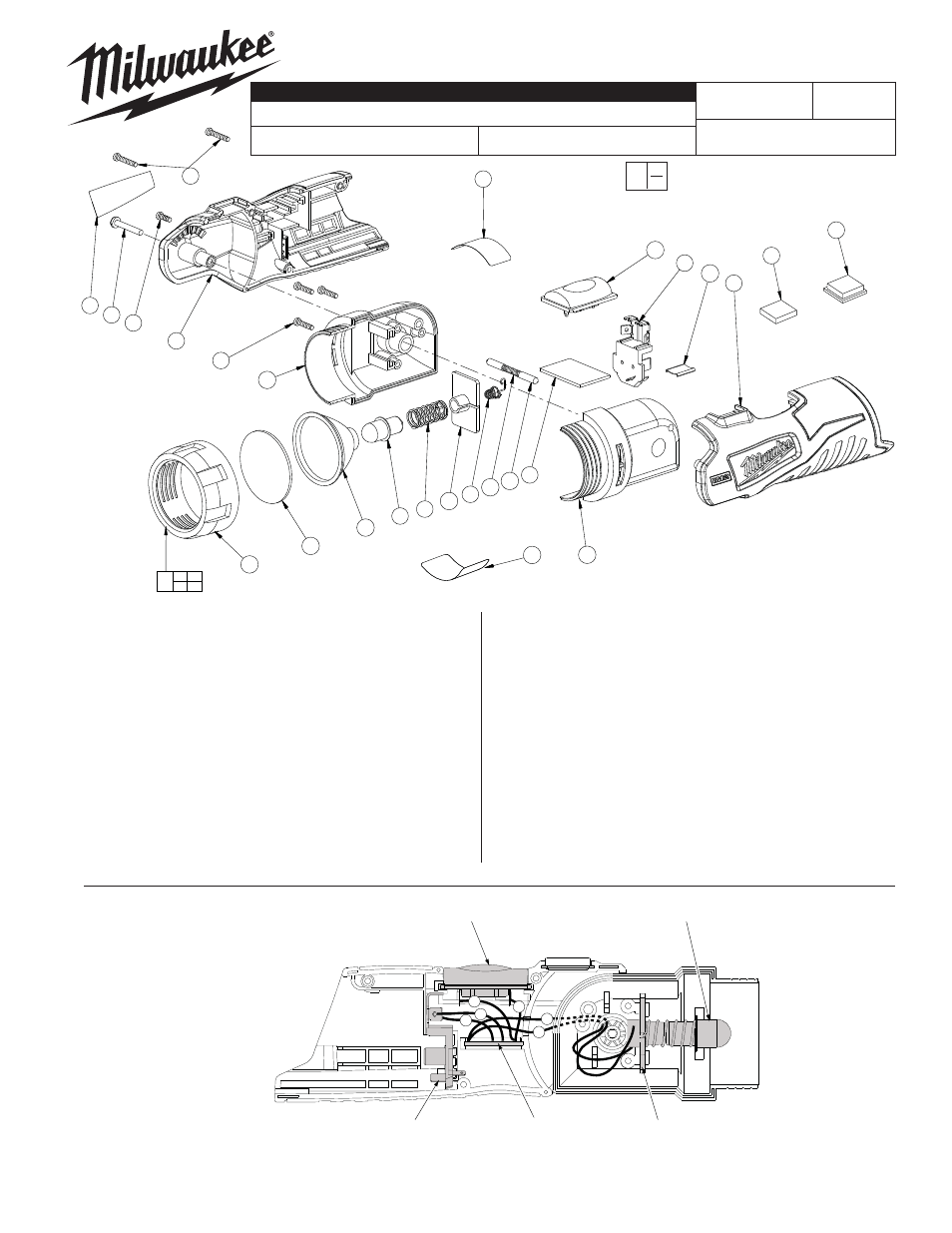
SERVICE PARTS LIST
MILWAUKEE ELECTRIC TOOL CORPORATION
13135 W. LISBON RD., BROOKFIELD, WI 53005
Drwg. 1
BULLETIN NO.
STARTING
SERIAL NO.
WIRING INSTRUCTION
DATE
SPECIFY CATALOG NO. AND SERIAL NO. WHEN ORDERING PARTS
CATALOG NO.
FIG.
PART NO. DESCRIPTION OF PART
NO. REQ.
1 10-20-2705 Warning
Label
(1)
2
12-20-2105
Service Nameplate Kit
(1)
3 ---------------
PCB
Assembly
(1)
4
49-81-0020
12/14.4 Volt Light Bulb (Pkg. of 2)
(1)
5 ---------------
Connector
Block
(1)
6 ---------------
Negative
Contact
(1)
7 ---------------
Positive
Contact
(1)
8
---------------
Handle Halve - Right
(1)
9
---------------
Handle Halve - Left
(1)
10
---------------
Housing - Right
(1)
11
---------------
Housing - Left
(1)
12 ---------------
Bezel
(1)
13 ---------------
Compression
Spring
(1)
14 ---------------
Contact
Holder
(1)
15 ---------------
Lens
(1)
16 ---------------
Detent
Pin
(2)
54-06-8910
CORDLESS 12 VOLT WORKLIGHT
49-24-0145
B51A
Sept. 2008
0
00
EXAMPLE:
Component Parts (Small #) Are Included
When Ordering The Assembly (Large #).
NOTE: The use of a soft cloth is recommended
when installing lightbulbs. Direct contact with oils or
other contamination can shorten the life of lightbulbs.
23
10
2
25
24
8
26
12
15
17
4
6
14
7
13
16
3
22
11
1
18
5
19
9
20
21
12 15
17
27
FIG.
PART NO. DESCRIPTION OF PART
NO. REQ.
17 ---------------
Refl ector
(1)
18
---------------
Push Button Switch
(1)
19 ---------------
Retainer
Clip
(1)
20 ---------------
Magnet
(1)
21 ---------------
Protective
Cover
(1)
22
10-20-2750
Temperature Warning Label
(1)
23
---------------
6 x 15 Pan Hd. T-9 Screw
(2)
24
---------------
6 x 8 Pan Hd. T-9 Screw
(1)
25
---------------
M3 x 20 Pan Hd. T-9 Screw
(1)
26
---------------
6 x 12 Pan Hd. Phillips Screw
(3)
27 31-58-0710
Bezel
Assembly
(1)
Connector
Block
Push Button
Switch
PCB
Assembly
Light Bulb
Contact
Holder
2
1
3
4
6
5
1 Black From PCB to Negative Contact
2 Red
From PCB to Positive Contact
3 Red
From PCB to Push Button Switch
4 Red
From PCB to Push Button Switch
5 Yellow From PCB to Connector Block
6 Black From PCB to Connector Block