Philips Magnavox LSS-40CP User Manual
Page 11
11
NOTE: DIAGRAMS & ILLUSTRATIONS NOT TO SCALE.
WARRANTY
Your gas appliance is covered by a limited
twenty year warranty. You will find a copy of
the warranty accompanying this manual.
Please read the warranty to be familiar with
its coverage.
Retain this manual. File it with your other docu-
ments for future reference.
REPLACEMENT PARTS
A complete parts list is found at the end of this
manual. Use only parts supplied from the
manufacturer.
Normally, all parts should be ordered through
your Lennox distributor or dealer. Parts will be
shipped at prevailing prices at time of order.
When ordering repair parts, always give the
following information:
PRODUCT REFERENCE INFORMATION
We recommend that you record the following important information about your fireplace. Please
contact your Lennox dealer for any questions or concerns. For the number of your nearest Lennox
dealer, please call 800-731-8101
Your Fireplace's Model Number _______________________________________
Your Fireplace's Serial Number ________________________________________
The Date On Which Your Fireplace Was Installed __________________________
The Type of Gas Your Fireplace Uses ___________________________________
Your Dealer's Name _________________________________________________
If you encounter any problems or have any
questions concerning the installation or appli-
cation of this system, please contact your dis-
tributor, or Lennox directly:
LHP
1110 West Taft Avenue
Orange, CA 92865
1. The model number of the appliance.
2. The serial number of the appliance.
3. The part number.
4. The description of the part.
5. The quantity required.
6. The installation date of the appliance.
Glowing Embers (Rockwool) Placement
Refer to the detailed glowing embers place-
ment instructions provided in the LOG PLACE-
MENT GUIDE accompanying this document.
Honeywell RF Control Millivolt Appliance
Pilot Checkout
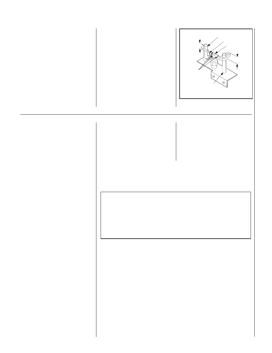
Pilot Inspection
To obtain proper operation, it is imperative that
the pilot and burner's flame characteristics are
steady, not lifting or floating (
see Figure 11 ).
Typically, the top 3/8" of the thermopile should be
engulfed in the pilot flame (
Figure 11 ).
Figure 11
Thermopile
Ignitor Rod
Hood
³⁄₈" Min
(9 mm)
Thermopile
MILLIVOLT HONEYWELL
Pilot
Nozzels
³⁄₈" Min
(9 mm)
To adjust pilot burner; (by a qualified service
technician)
1. Remove pilot adjustment cap.
2. Adjust pilot screw to provide properly sized
flame.
3. Replace pilot adjustment cap.
The primary air shutter is set at the factory and
should only be adjusted, if necessary, by a
qualified service technician.