Ex rt cla module, B. rack installation – MGE UPS Systems EX RT CLA User Manual
Page 4
EX RT CLA Module
4
86-86000-04 AO
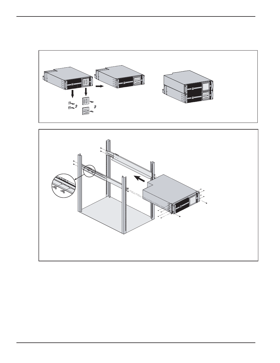
STEP 3 EX RT CLA Module Rack Configuration (Requires optional Rail Kits 86001, 86002. See
System Installation and User Manual for details.)
EX RT CLA Module Installation
3. Install Front Mounting Brackets
to each side of the CLA Module.
3
2
1
1
1
1
4
4
3
2. Attach rails together
with provided wing nuts.
1. Attach both rails to rear and front
of rack chassis with supplied screws.
4. Use caution when sliding unit into rack mount,
secure unit to rack with supplied screws.
(For this step, it is possible to adjust the position
of both front mounting brackets.)
B. Rack Installation
www.mg
eups.co
m
E X 1
1 R T
OFF
ON
E
X
1
1
R
T
O
F
F
O
N
w
w
w
.m
g
e
u
ps
.c
o
m
w
w
w
.m
ge
u
ps
.c
o
m
E
X
1
1
R
T
O
F
F
O
N
E X 1
1 R T
OFF
ON
www.mg
eups.co
m
1
2
3
FINISHED PANEL
(rack orientation)
1
2
3
A.
Prepare the front panel logo and LCD display for rack orientation,
Apply to all modules. Power Module shown.
Stack-up sequence in Rack configuration
www.mg
eups.co
m
OFF
ON
EX 11 R
T
www.mg
eups.co
m
EX RT T
ransfor
mer
2. POWER MODULE
(bottom, EX 5/7/11 RT)
1. EX RT CLA MODULE
(Top, EX 5/7/11 RT)