Front panel features, Rear panel features – MACKIE UP4000 User Manual
Page 2
0
50V
70V
100V
POWER OUTPUTS
0
25V
POWER OUTPUTS
4
+
D.C. FUSE
POWER INPUT
24V D.C.
VOLTAGE
SELECTOR
LINE
50/60 Hz-115/230V
-
INPUT
COMMANDS
0dB
20dB
ON
OFF
PRIORITY
GND
UNBALANCED IN
GND
H.P.
FILTER
BALANCED
IN
L.P.
STAND
BY
SENSITIVITY
GND
PARALLEL OUT
OVERL.
300mA.
max
CONCEIVED, DESIGNED, AND MANUFACTURED BY MACKIE INDUSTRIAL • MADE IN ITALY • PATENTS PENDING • COPYRIGHT ©1999
SERIAL NUMBER
MANUFACTURING DATE
RISK OF ELECTRIC SHOCK
DO NOT OPEN
REPLACE WITH THE SAME TYPE FUSE AND RATING.
DISCONNECT SUPPLY CORD BEFORE CHANGING FUSE
UTILISE UN FUSIBLE DE RECHANGE DE MÊME TYPE.
DEBRANCHER AVANT DE REMPLACER LE FUSIBLE
WARNING:
TO REDUCE THE RISK OF FIRE OR ELECTRIC SHOCK, DO NOT
EXPOSE THIS EQUIPMENT TO RAIN OR MOISTURE. DO NOT REMOVE COVER.
NO USER SERVICEABLE PARTS INSIDE. REFER SERVICING TO QUALIFIED PERSONNEL.
CAUTION
AVIS:
RISQUE DE CHOC ELECTRIQUE — NE PAS OUVRIR
THE FOLLOWING ARE TRADEMARKS/REGISTERED TRADEMARKS OF MACKIE DESIGN INC.: "MACKIE", "MACKIE INDUSTRIAL", & THE "RUNNING MAN" FIGURE
LOW
EQ
HIGH
VOLUME
0
10
8
2
1
3
4
5
6
7
9
8
4
2
0
2
4
8
-10
+10
6
6
8
4
2
0
2
4
8
-10
+10
6
6
POWER
PEAK
OVERLOAD SIGNAL
ON
STD-BY
UP 4161 - P.A. AMPLIFIER
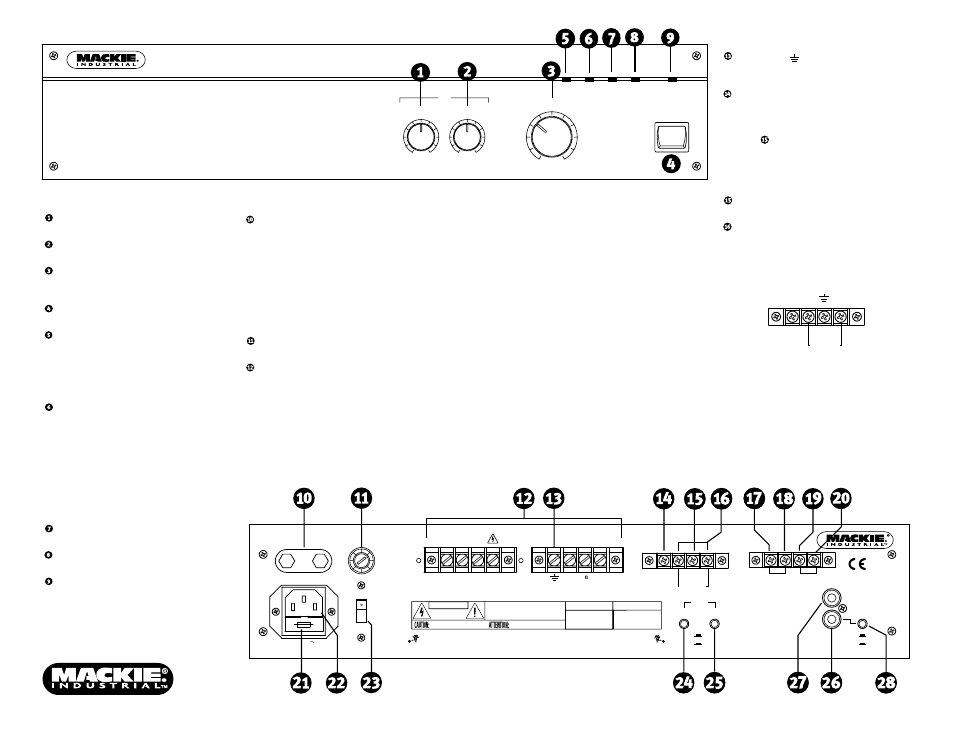
Front Panel Features
LOW EQ is a shelving filter that provides
12 dB of boost and cut below 100Hz.
HIGH EQ is a shelving filter that provides
12 dB of boost and cut above 10kHz.
VOLUME is a master volume control used
to adjust the overall volume of the signal
at the POWER OUTPUTS.
Use the
POWER switch to turn the UP4000
Series on and off.
The
STD-BY indicator lights when the
amplifier is in standby mode.
Note: Standby mode is disabled by
default. An internal jumper (J1 on the
input board) must be changed to enable
standby mode. See Figure 1 on back page.
The
OVERLOAD indicator lights when the
amplifier is operating in overload, a
condition generally caused by a problem
on the speaker line. When the amplifier is
switched on, the OVERLOAD light comes
on for a few seconds. This is normal and
does not indicate a problem.
When the OVERLOAD circuit is activated,
the OVERL. 300mA output on the
COMMANDS terminal strip is also activated.
The
SIGNAL indicator lights when a signal
is present at the POWER OUTPUTS.
The
PEAK indicator lights when the output
signal is approaching clipping.
The
ON indicator lights when the AM4000
is turned on and ready for operation.
Rear Panel Features
POWER INPUT provides a means to
connect an external 24 VDC power supply
or battery as an alternative or backup
power source. The AM4000 Series
seamlessly switches to the backup supply
if there's an AC power loss. When both AC
power and 24 VDC power are connected,
the DC power is switched off.
Note: The unit is not equipped with
battery charging capability.
The
D.C. FUSE protects the DC POWER INPUT
circuit. Replace with the same type fuse only.
POWER OUTPUTS are screw-terminal
connections for connecting speakers to the
4-ohm, 25V, 50V, 70V, or 100V outputs.
WARNING: To prevent the risk of electric
shock, never touch the bare wires coming
from the output terminals of the amplifier
when it is switched on. When all
connections have been made, insulate
the output terminals of the amplifier
using the protective cover provided.
Constant-Impedance Output
The total impedance of the speakers and
cable connected to the "4
Ω" constant-
impedance output should be 4 ohms.
Connect the "4
Ω" terminal to the "+"
(HIGH) speaker terminal, and the "0"
terminal to the "–" (LOW) speaker terminal.
Constant-Voltage Output
In a constant-voltage system, each
speaker must be equipped with a line
transformer having an input voltage equal
to that of the line (e.g., 25V, 50V, 70V, or
100V). Typically, these line transformers
have selectable power taps (i.e., 2.5W,
5W, 10W) for connecting to the constant-
voltage line.
CAUTION: The sum of the
wattage values of the speakers must not
exceed the output power of the amplifier.
Connect the appropriate
POWER OUTPUT
voltage terminal to the "+" (HIGH) leg and
the "0" terminal to the "–" (LOW) leg of the
distributed speaker system.
The ground (
) terminal is internally
connected to the chassis and safety
ground on the AC linecord.
The
PRIORITY terminal activates the
priority function for the BALANCED IN by
using an external normally-open switch to
short-circuit the PRIORITY terminal to the
GND
(ground) terminal. When the
PRIORITY function is enabled, the
UNBALANCED IN is muted (no signal from
the UNBALANCED IN is transmitted to the
outputs).
The
GND terminal is the common connec-
tion point for BALANCED IN and PRIORITY.
The
BALANCED IN terminals are the main
inputs for the amplifier and accept a
balanced line-level signal (0 dBu nominal).
Connect signal high (+) and low (–) as
indicated below:
+
–
PRIORITY
GND
BALANCED
IN
The BALANCED IN has a priority function,
and attenuates the UNBALANCED IN when
closing an external normally-open switch
connected between the PRIORITY terminal
to the GND (ground) terminal.