Shave plate and skid shoes, Belt removal and replacement – MTD 31AE633E401 User Manual
Page 14
14
operation, remove rear cover. Lubricate any chains,
sprockets, gears, bearings, shafts, and shifting
mechanism at least once a season. Use engine oil or a
spray lubricant. Avoid getting oil on rubber friction
wheel and aluminum drive plate. Refer to Figure 14.
Gear Case
The gear case is lubricated with grease at the factory
and does not require checking. If disassembled for any
reason, lubricate with two ounces of Shell Alvania™
grease EPR00, part number 737-0168. Before
reassembling, remove old sealant and apply Loctite™
5699 or equivalent.
IMPORTANT:
Do not overfill the gear case. Be sure the
vent plug is free of grease in order to relieve pressure.
Traction Control / Auger Control Lock
The cams on the ends of the control rods which
interlock the traction drive and auger drive clutches
must be lubricated at least once a season or every
twenty five hours of operation. The cams can be
accessed beneath the handle panel. Use a multi-
purpose automotive grease.
Figure 19
SECTION 7: SERVICE
WARNING:
Before servicing, repairing, or
inspecting, disengage all clutch levers and
stop engine. Wait until all moving parts have
come to a complete stop. Disconnect spark
plug wire and ground it against the engine to
prevent unintended starting.
Shave Plate and Skid Shoes
•
The shave plate and skid shoes on the bottom of
the snow thrower are subject to wear. They should
be checked periodically and replaced when
necessary.
•
To remove skid shoes, remove the four carriage
bolts, belleville washers and hex nuts which attach
them to the snow thrower. Reassemble new skid
shoes with the four carriage bolts, belleville
washers (cupped side goes against skid shoes)
and hex nuts. Make certain the skid shoes are
adjusted to be level.
•
To remove shave plate, remove the carriage bolts,
belleville washers and hex nuts which attach it to
the snow thrower housing. Reassemble new shave
plate, making sure heads of the carriage bolts are
to the inside of the housing. Tighten securely.
Belt Removal and Replacement
WARNING:
Disconnect the spark plug wire
from the spark plug and ground.
Auger Belt(s)
•
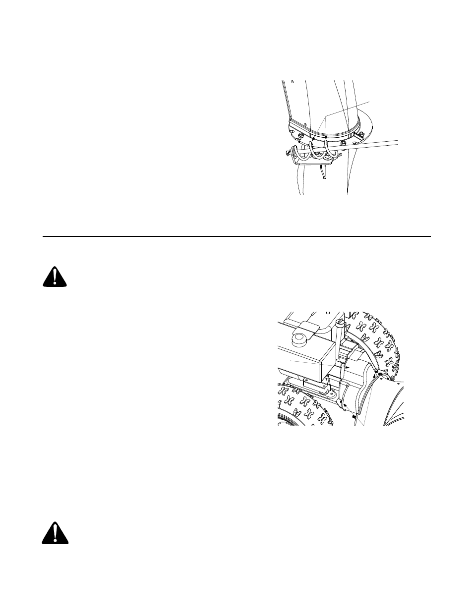
Remove the plastic belt cover on front of the engine
by removing the two self-tapping screws. See
Figure 20.
Figure 20
•
Drain the gasoline from the snow thrower, or place
a piece of plastic film under the gas cap.
•
Tip the snow thrower up and forward so that it rests
on its auger housing.
•
Remove six self-tapping screws from the frame
cover underneath the snow thrower.
•
Roll the front and rear auger belts off the engine
pulley. See Figure 21.
NOTE: Model E633 has only one auger belt. Disregard
any instructions regarding the second auger belt if you
have this model of snow thrower.
Lube spiral
and chute base
Self-Tapping Screws
Belt
Cover