Goodman Mfg Split System Condensing Units IO-101G User Manual
Page 3
3
IO-101G
06/04
This “close to the wall” application minimizes exposed
tubing and wiring and reduces the space for children to
run around the unit. This will help to avoid possible
damage to the tubes or wiring and/or personal injury.
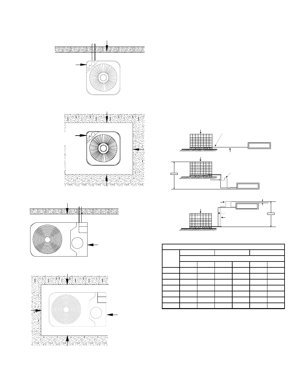
Service Access
18" Min.
Service Access
18" Min.
10" Min.
10" Min.
10"
10"
FIGURE 1
Service Access
18" Min.
10" Min.
Service Access
18" Min.
10" Min.
10" .
10" .
FIGURE 2
Close to the wall application assures free, unobstructed
air to the other two sides. In more confined application
spaces, such as corners, provide a minimum 10” clearance
on all air inlet sides. Allow 18” minimum for service access
to the compressor compartment and controls.
The top of the unit should be completely unobstructed. If
units are to be located under an overhang, there should
be a minimum of 36” clearance and provisions made to
deflect the warm discharge air out from the overhang.
LOCATION
If unit is to be located under an overhang, there should be
a minimum of 36” clearance and provisions made to deflect
the water discharge air out from the overhang. If the
outdoor unit is mounted above the air handler, the
maximum lift should not exceed 70’ (suction line). If air
handler is mounted above condensing unit, the lift should
not exceed 50’ (liquid line.). Refer to Figure 3 and Table 1
for maximum refrigerant line lenghts.
PITCH SUCTION LINE TOWARD OUTDOOR
UNIT 1/2" FOR EVERY 10' OF LINE
INDOOR UNIT ABOVE OR
LEVEL TO OUTDOOR UNIT
INDOOR UNIT
LIQUID LINE
OUTDOOR UNIT
OUTDOOR UNIT
INDOOR UNIT
70' MAX.
LIQUID LINE
SUCTION LINE OIL TRA PS
W H EN INDOOR UNIT IS 4
FEET OR MORE BELOW
OUTDOOR UNIT
INDOOR UNIT BELOW
OUTDOOR UNIT
OUTDOOR UNIT
ADDITIONAL SUCTION LINE OIL TRA P
FOR EA CH 2 0 ' R I SE OF PIPE
INDOOR UNIT
50' MAX.
8 '
SUCTION LINE
INVERTED LOOP
LIQUID LINE
FIGURE 3
Cond
Unit
Tons
Suct
Liq
Suct
Liq
Suct
Liq
1 1/2
5/8
1/4
3/4
3/8
3/4
3/8
2
3/4
3/8
3/4
3/8
3/4
3/8
2 1/2
3/4
3/8
3/4*
3/8
7/8
1/2
3
3/4
3/8
3/4**
3/8
7/8
1/2
3 1/2
3/4
3/8
7/8***
3/8
1 1/8
1/2
4
7/8
3/8
1 1/8
3/8
1 1/8
1/2
5
7/8
3/8
1 1/8
3/8
1 1/8
1/2
Line Diameter (In. OD)
REFRIGERANT LINE LENGTH (Ft)
0-24
25-49
50-74***
* 7/8" required for full ratings
** 1 1/8" required for full ratings
TABLE 1
The condensing unit must be mounted on a solid, level
foundation, i.e. pre-formed concrete slab or other suitable
base. For rooftop application, make sure the building
construction can support the weight and that proper