Control circuit diagram (standard control), Wiring for additional sensors (optional) – Greenheck Fan Greenheck 474750 User Manual
Page 5
5
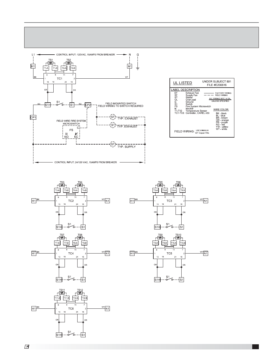
Digital Temperature Interlock
Control Circuit Diagram (Standard Control)
This Control Panel only provides control power to
signal operation of supply and exhaust starters.
Starters are NOT provided by manufacturer.
Starters to be provided by, wired and mounted by others.
Wiring for additional sensors (optional)
This is an example of a generic wiring diagram for standard control. This diagram has 12 sensors
which provide temperature interlock function for two exhaust fans and one supply fan.
(All starters provided by others, external to this control box).
®