Dcl c f f – GSW 5065 User Manual
Page 12
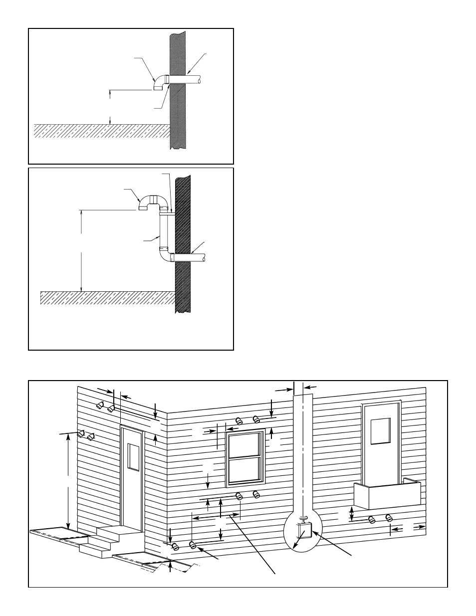
Horizontal Vent Terminal Installations
The following requirements are illustrated in Figure 10:
1. ("A") Minimum 2.1m (7 ft.) above a paved sidewalk or
paved driveway that is located on public property.
2. ("B") Minimum 900mm (3 ft.) above any forced air or
mechanical air supply inlet located within 1.8m (6 ft.)
horizontally (Canada) or 3m (10 ft.) (U.S.A.).
3. ("C") Within 900mm (3 ft.) of any gas service regulator
vent outlet.
4. ("D") Minimum 900 mm (3ft) horizontally of the vertical
centerline above the regulator vent outlet to a maximum
vertical distance of 4.5m (15ft).
5. ("E") Minimum 305mm (1 ft.) above grade level or antic-
ipated snow level.
6. ("F") Within 305mm (1 ft.) of any window or door that
can be opened, of any non-mechanical air supply inlet
or of the combustion air inlet of any other appliance.
7. ("G") Minimum 305mm (1 ft.) distance between the top
of the vent termination and the underside of a veranda,
porch or deck.
8. ("H") The manufacturer recommends the vent termina-
tion shall not be mounted directly above or within
900mm (3 ft.) horizontally from an oil tank or gas meter
to avoid potential freeze-up from condensation.
9. ("J") The manufacturer recommends the vent terminal
not to be installed closer than 900mm (3 ft.) from an
inside corner or 610mm (2 ft.) from outside corner on an
"L" shaped structure.
Vertical Vent Terminal Installation
Important: When terminating the vents through a roof, the
following specifications pertaining to terminal location must
be followed.
1. The exhaust vent termination shall extend at least
450mm (18 in.) above the roof or snow accumulation
level.
BRACKET
VENT RISER
SEALANT
ATTACH 90°
TERMINATION
ELBOW
305mm
(12 in.)
MIN.
CONDENSATION
TRAP & DRAIN
GROUND LEVEL OR MAXIMUM SNOW LINE
VENT PIPING MAY BE SLOPED IN ANY DIRECTION, AS LONG AS A WATER
TRAP IS NOT CREATED IN THE VENTING SYSTEM. THE SLOPE SHOULD BE
KEPT TO A MINIMUM SO AS NOT TO EXERT ANY UNDUE STRESS ON THE
PIPE.
Figure 9 Installation Of Fabricated Vent Riser.
SEALANT
SEALANT
ATTACH 90°
TERMINATION ELBOW
305mm
(12 in.)
MIN.
GROUND LEVEL OR MAXIMUM SNOW LINE
Figure 8 Vent Termination Exterior Installation
A
E
F
F
Figure 10 Vent Terminal Installations
J
G
GAS METER AND
REGULATOR
MECHANICAL AIR
SUPPLY INLET
1.8m (6 ft.) (Canada),
3m (10 ft.) (U.S.A.)
D
CL
C
F
F
F
B
– 12 –