Bandsaw controls – Grizzly G1148 User Manual
Page 14
-14-
G1148 15" Bandsaw
SECTION 5: ADJUSTMENTS
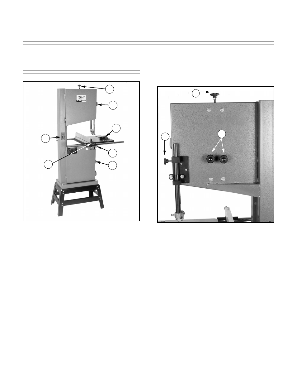
Bandsaw Controls
B
E
A
F
D
A
C
General control and adjustment locations are
shown in Figure 8 above and are described in
this section.
A. These two guard locking knobs (#46)
secure the upper and lower wheel covers
(#24, #25). The covers are only opened to
change a blade or make an adjustment to
blade tracking. Blade changing and tracking
will be explained later in this section.
B. This is the toggle switch (#16) that the con-
trols the motor. Power is controlled by up
and down movement.
C. This handle (#107) and knob (#91) locks
the rip fence in place.
D. These star knobs (#77) are used to lock the
table in position.
E. The miter gauge slides in the milled groove
in the table and can be set at 45° left and
right. Use the miter gauge for crosscutting
and miter-cutting.
Now, direct your attention to the controls located
around the upper part of the saw. See Figure 9.
F. This knob (#8) is used to control blade ten-
sion. Turning clockwise (from the front)
increases tension;
counter-clockwise
decreases tension.
G. These knobs (#14) control blade tracking
by setting the angle of the upper wheel.
Note that the knobs have locking nuts in
place.
H. This knob (#93) locks the upper blade guide
assembly (assembled around #58) in posi-
tion. The upper guide should be adjusted to
within
1
/
4
" of the workpiece for optimum
blade support.
Figure 9. Upper Controls.
F
G
H
Figure 8. General controls.