Upper guides, Wheel alignment – Grizzly G1258 User Manual
Page 13
G1258 20" Bandsaw
-11-
Normally
Steps 1-4
are implemented prior to
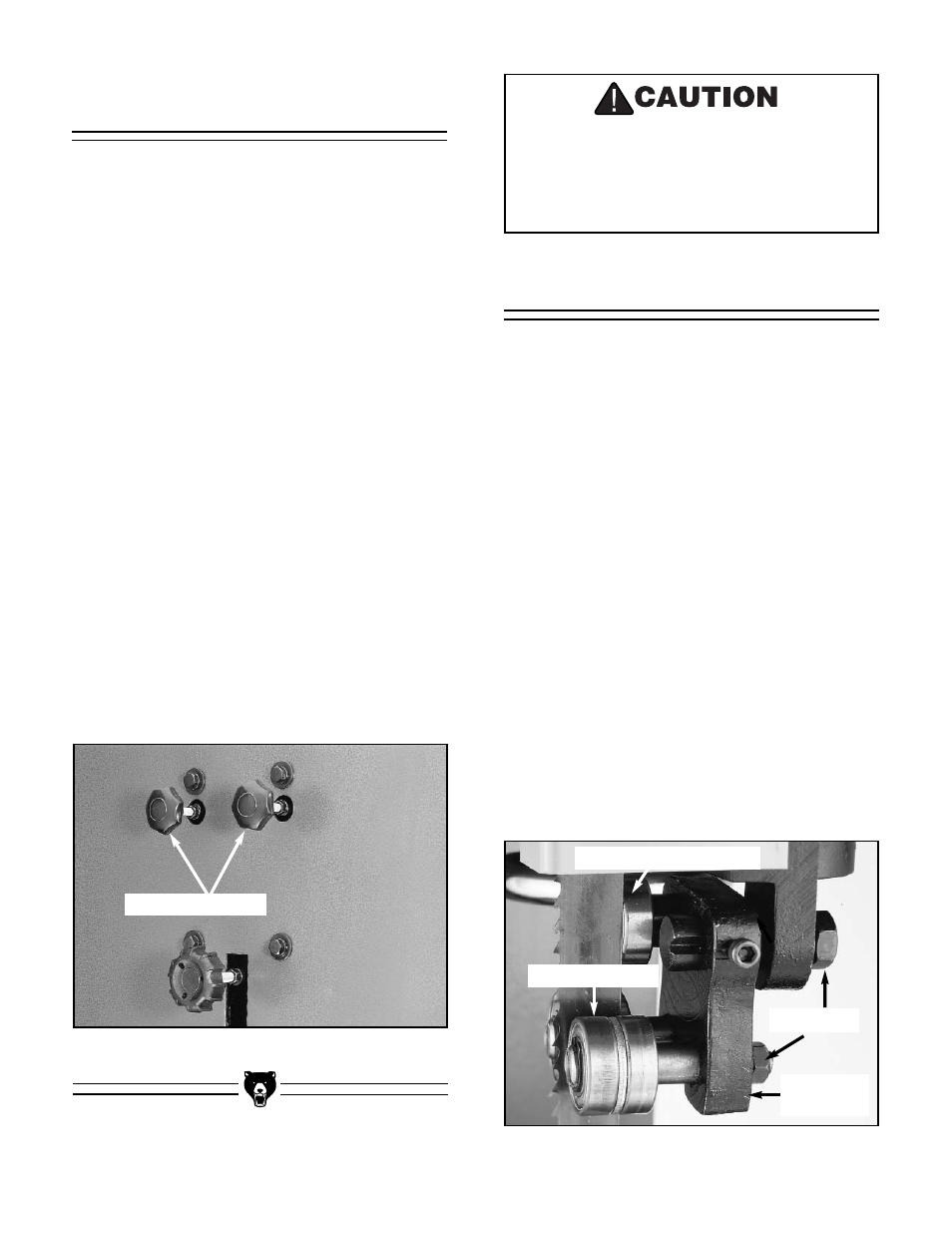
installing a new blade. To adjust the upper
guides:
1.
Loosen the bearing guide shaft lock nuts.
2.
The bearing guides are mounted on an
eccentric shaft. With a regular screwdriver,
rotate the guides away from the blade.
3.
Loosen the cap screw holding the bearing
back-up shaft in place and slide the bearing
back-up away from the blade.
4.
Loosen the cap screw holding the blade
assembly in place and slide it back away
from the blade.
5.
Install your blade of choice. Track and ten-
sion as per the instructions in this manual.
6.
Move the blade guide assembly so the bear-
ing guides are
1
⁄
16
" behind blade gullets.
Tighten the guide assembly.
Figure 6
shows upper blade guide assembly.
Lock Nuts
Rear Support Bearing
Bearing Guides
Guide
Assembly
Figure 5.
Wheel alignment adjusting knobs.
Adjusting Knobs
Which ever direction one knob is turned,
the other knob must be turned the same
amount in the opposite direction. If this
step is not observed, the tracking mecha-
nism will be put in a bind.
Upper Guides
The upper wheel can be adjusted to correct for
any deviation in parallelism. Although this has
been set at the factory, it is a good idea to check
it occasionally to assure good and proper opera-
tion of your bandsaw. To adjust the wheel paral-
lelism:
1.
Open the top and bottom covers.
2.
Measure the distance the bottom wheel is
from the bandsaw frame, front to back.
Usually the Lower wheel will be slightly at an
angle to the bandsaw frame. Make note
which way the wheel is skewed and by how
much.
3.
Now measure the top wheel, front to back.
Ideally, you want the top wheel to match the
angle at which the bottom wheel is set.
For
example:
if the you determine the bottom
wheel is tapered to the front by
1
⁄
16
'', the top
wheel should be adjusted so it is tapered in
the same direction by the same amount.
4.
The knobs to adjust the top wheel are locat-
ed at the back of the bandsaw. Refer to
Figure 5.
Loosen the check nuts and adjust
as necessary.
Wheel Alignment