Circuit description – Goldstar MONOCHROME MONITOR MBM-2105GIA User Manual
Page 3
CIRCUIT DESCRIPTION
1.
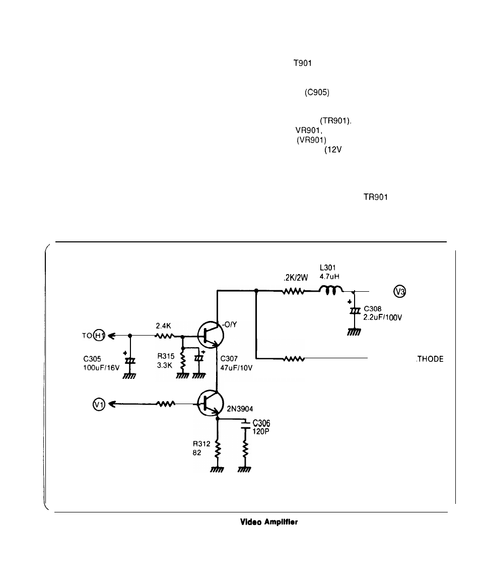
VIDEO AMPLIFIER
2. POWER SUPPLY
The Fig. 3 details the cascade video amplifier.
Video amplification is provided by the TR303 and
TR304. TR303 and TR304 are connected in a
cascade configuration. TR303 operates as a
common emitter and TR304 operates in the
common base configuration. This minimized the
miller effect input capacitance and the difining
breakdown parameter for TR303 which becomes
BVCBO as opposed to BVCEO.
This enables selection of a higher speed/lower
breakdown transistor to be used in the video
amplifier.
The emitter of TR304 is driven by the collector of
TR303 which is a high frequency transistor.
Overall voltage gain for the stage is determined
by the ratio of R312 to R316. Bandwidth is within
The 120V AC line voltage is applied to the primary
of the
where it is stepped down through the
secondary winding to approximately 17V (AC).
After passing through the bridge rectifier circuit
and filter
the regulated DC supply voltage
is approximately 18V (DC). The 18V unregulated
B+ voltage is applied directly to the collector of the
B+ regulator
A voltage divider network
(R905,
R906) in which the B+ adjustment
control
is used to establish the desired
operating level
DC). When AC input voltage
variations occur, a correction voltage is produced
at the base of TR903 and is coupled directly to the
base of the error amplifier (TR902). This correction
voltage is then passed from the emitter of TR902
directly to the base of
and B+ voltage
regulation is then accomplished.
3dB to 32 MHz.
TO
R316
1
l
TO
T R 3 0 4
R314
KTC2229
l
TO
R317
3 3 0
T R 3 0 3
R309
7 5
R313
4 7
CRT CA
Figure 3,