Important – GTO FM121 User Manual
Page 3
3
RED
BLK
Solar Panel Wires
18VAC
SOLAR
+
–
~
~
FM500, FM502, SW2500 Control Boards
RED
BLK
Solar Panel Wires
POWER IN
18VAC SOLAR
~ ~ – +
RED
BLK
Solar Panel Wires
FM700, FM702, SW1000, SW2000, SL1000, SL2000 Control Boards
SW2000/2002XL
,
SW3000/3200XL
,
SW4000/4200XL Control Boards
AUX
OUT
SOLAR
PANEL
18VAC
RED
BLK
Solar Panel Wires
FM
5350
SW1500 Control Boards
RED
BLK
Solar Panel Wires
SW3000/3200, SW4000/4200 Control Boards
18 VAC SOLAR RELAY OUT
~ ~ -
+
NC
NO
RLY-COM
J9
J2
J1
~
~
SOLAR
or
18 VAC
LOCK
GTO
AUX
GTO
TRANSF
LOCK
PWR
AUX
RLY
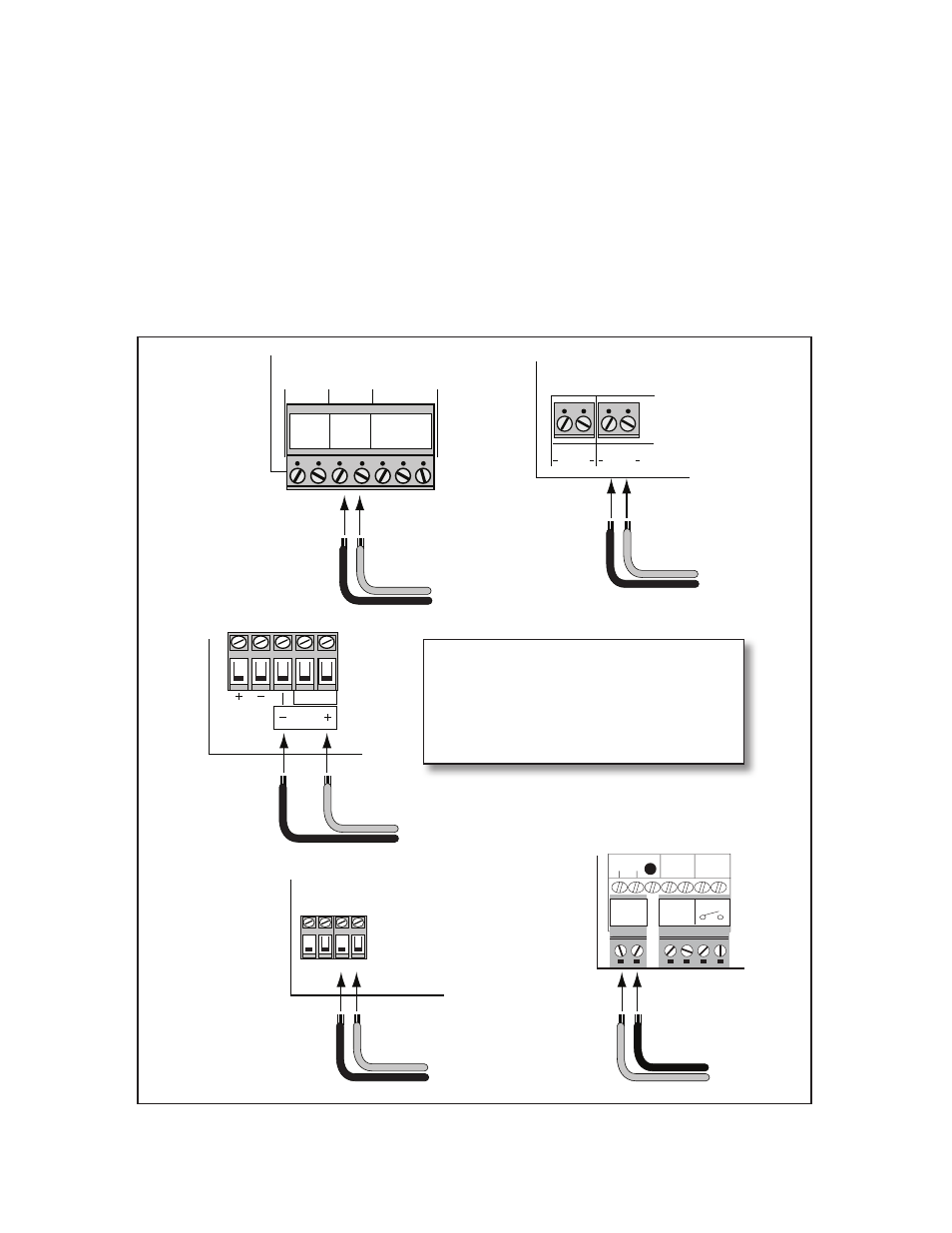
Step 3: All Mighty Mule and GTO/PRO DC powered gate operators have a POWER IN terminal on their control
boards marked SOLAR for connecting the solar panel wires. Below are various types of terminals on GTO/PRO
and Mighty Mule control boards, if your control board doesn't have this terminal, please call the GTO's Technical
Service Department at (800)543-1236 or (850)575-4144 for assistance.
Feed the free end of the solar panel wires into the control box and attach them to the SOLAR terminals on the
POWER IN terminal block on the control board. The RED solar panel wire goes to the (+) POSITIVE Solar ter-
minal and the BLACK solar panel wire goes to the (–) NEGATIVE Solar terminal. See diagram below.
IMPORTANT:
Improper installation of these wires will damage to the opener's control board.
Attach RED solar panel wire to the
SOLAR terminal marked
(+)
.
Attach BLACK solar panel wire to the
SOLAR terminal marked
(–)
.