GE Interlogix BusSecure User Manual
Page 13
BusSecure User Manual
Hardware Installation
0150-0263A / May 2003
13
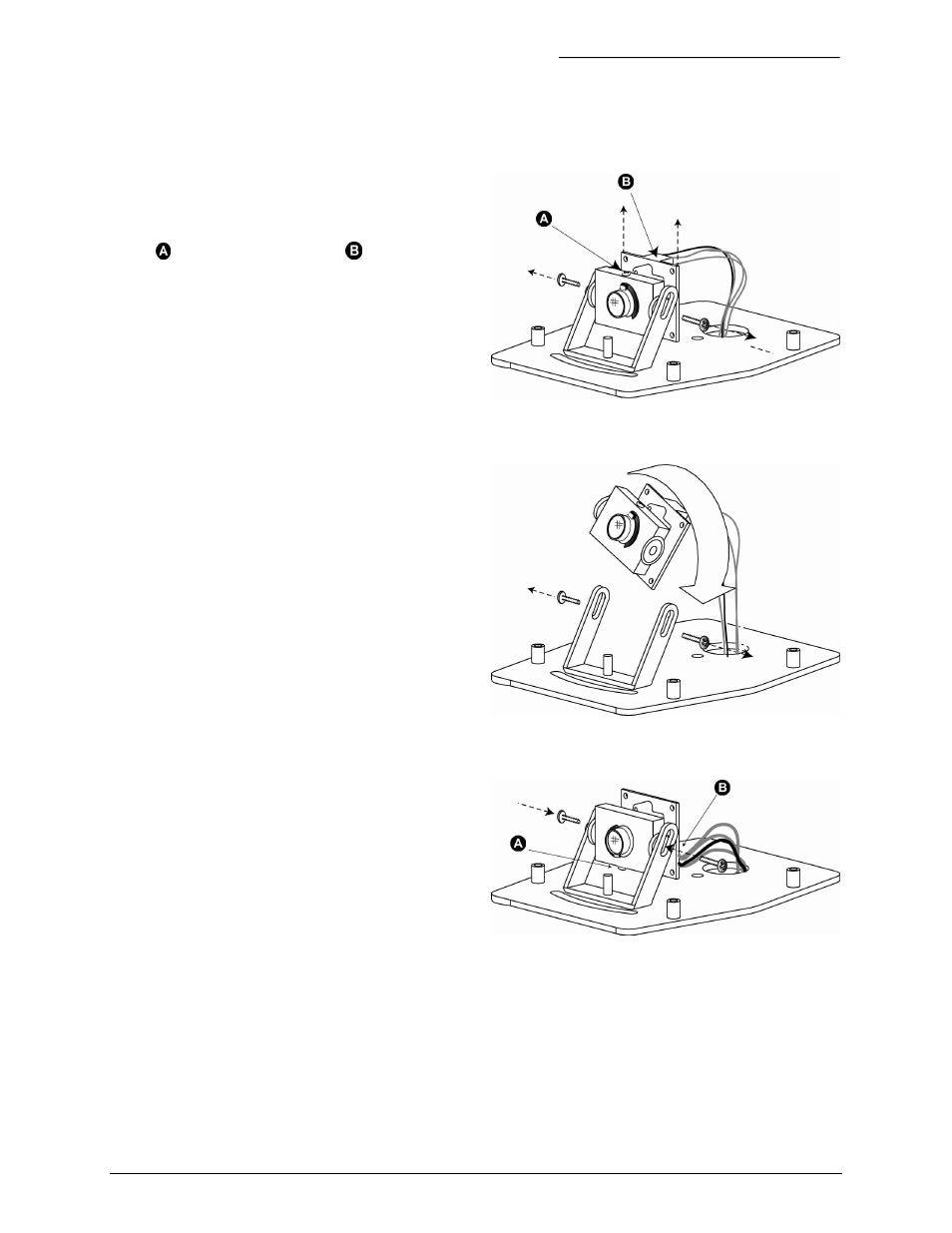
To adjust the camera according to where it will be mounted on the vehicle, perform the following:
1) Figure 13 shows orientation of a
camera for mounting on the curbside of
the bus, the backside of the bus, or in a
forward-facing position on the
dashboard. Note that the lens set screw
( ) and the wiring harness (
) are
positioned at the top of the camera.
2) For cameras mounted on the streetside
of the bus or surface-mounted facing
backward, remove the two side-set
screws, as shown in Figure 14, and lift
the camera out of its bracket.
3) Rotate the entire camera assembly
180º. See Figure 14.
4) Insert the camera into the bracket, and
replace set screws. The lens set screw
and the wiring harness should now be
positioned at the bottom of the camera.
See Figure 15.
Figure 13. Camera orientation for curbside mounting.
Figure 14. Rotating the camera for street-side orientation
Figure 15. Camera orientation for street-side mounting