Amplifier, Crossover, System – Genelec 2029A User Manual
Page 6: Digital
Genelec Oy, Olvitie 5
FIN - 74100 IISALMI, FINLAND
Phone:
+358 - 17 - 83881
Telefax:
+358 - 17 - 812267
Web:
http://www.genelec.com
E-mail:
Genelec document DR29101
COPYRIGHT GENELEC OY 1998
All data subject to change without prior notice
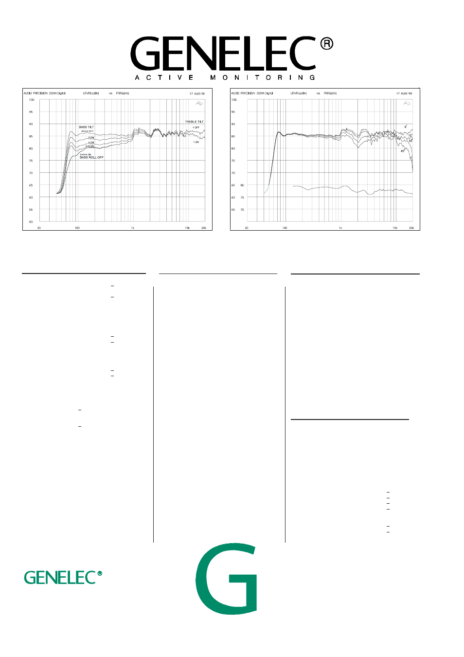
Figure 9: The effect of 'treble tilt', 'bass tilt' and 'bass roll-off' controls in free field.
Figure 10: Horizontal directivity characteristics and power response of 2029A Digital
in its vertical configuration measured at 1m in free field.
AMPLIFIER
AMPLIFIER
AMPLIFIER
AMPLIFIER
AMPLIFIER
SECTION
SECTION
SECTION
SECTION
SECTION
Bass amplifier output power with an 8 Ohm load:
40 W
Treble amplifier output power with an 8 Ohm load:
40 W
Long term output power is limited by driver unit
protection circuitry.
Amplifier system distortion at
nominal output:
THD
< 0.08%
SMPTE-IM
< 0.08%
CCIF-IM
< 0.08%
DIM 100
< 0.08%
Signal to Noise ratio, referred to full output:
Bass
> 90 dB
Treble
> 90 dB
Mains voltage:
100/200 or 115/230 V
Voltage operating range:
±10%
Power consumption:
Idle
9 VA
Full output
90 VA
CROSSOVER
CROSSOVER
CROSSOVER
CROSSOVER
CROSSOVER
SECTION
SECTION
SECTION
SECTION
SECTION
Inputs:
Input 1: XLR female, balanced 10 kOhm
Input 2:
1
/
4
" Jack socket, balanced 10 kOhm
Volume control:
Variable from Mute to -6 dBu for 100 dB SPL
output @ 1m
Subsonic filter below 68 Hz :
18 dB/octave
1091A Subwoofer output (input 2) at 100db SPL:
-23 dBu into 33kOhm load
Ultrasonic filter above 25 kHz:
12 dB/octave
Crossover frequency, Bass/Treble:
3.3 kHz
Crossover acoustical slopes:
24 - 32 dB/octave
Treble tilt control operating range:
0 to -2 dB @ 15 kHz
Bass roll-off control operating in a -6 dB step @ 85 Hz
(to be used in conjunction with the 1091A subwoofer)
Bass tilt control operating range in -2 dB steps:
0 to -6 dB @ 150 Hz
The 'CAL' position is with all tone controls set to 'off'
and the input sensitivity control to maximum (fully
clockwise).
SYSTEM
SYSTEM
SYSTEM
SYSTEM
SYSTEM
SPECIFICATIONS
SPECIFICATIONS
SPECIFICATIONS
SPECIFICATIONS
SPECIFICATIONS
Lower cut-off frequency, -3 dB:
< 68 Hz
Upper cut-off frequency, -3 dB:
> 20 kHz
Free field frequency response of system:
70 Hz - 18 kHz (± 2.5 dB)
Maximum short term sine wave acoustic output on axis
in half space, averaged from100 Hz to 3 kHz:
@ 1m
> 100 dB SPL
@ 0.5m
> 106 dB SPL
Maximum long term RMS acousticoutput in same
conditions with IECweighted noise (limited by driver unit
protection circuit):
@ 1m
> 98 dB SPL
@ 0.5m
> 104 dB SPL
Maximum peak acoustic output per pair on top of
console,
@ 1 m from the engineer with music material:
> 110 dB
Self generated noise level in free field @ 1m on axis:
< 10 dB
(A-weighted)
Harmonic distortion at 85 dB SPL @ 1m on axis:
Freq:
75...150 Hz
< 3%
> 150 Hz
< 1%
Drivers:
Bass
130 mm (5") cone
Treble
19 mm (
3
/
4
") metal dome
Both drivers are magnetically shielded.
Weight:
5.7 Kg
(12.5 lb)
Dimensions:
Height
247 mm
(9
3
/
4
")
Width
151 mm
( 5
15
/
16
")
Depth
191 mm
(7
1
/
2
")
DIGITAL
DIGITAL
DIGITAL
DIGITAL
DIGITAL
SECTION
SECTION
SECTION
SECTION
SECTION
Word length:
24 bits
Input format:
IEC958, S/P-DIF, EIJAC CP-340
Input termination impedance:
75 ohms
Input sampling rate:
25-55 kHz (no de-emphasis)
44.1 and 48 kHz (using
de-emphasis)
Jitter resiliance:
0.15 unit intervals
Dynamic range:
>101 dB (A weight, triangular
PDF dither, 20 bit data)
De-emphasis:
50/15us, automatic
Recovered clock jitter:
200 picoseconds RMS typical